The program is designed to calculate the optimum cross-section and perform strength check of slender struts strained for buckling. The program includes:
The calculation is based on data, procedures, algorithms (Johnson, Tetmajer,
Euler, Secant) and data from specialized literature and AISC,
ISO, DIN and BS standards.
List of standards (DIN 1025, 1026, 1028, 1029, 1024, AISC W, S, C, L, LU ... )
![]()
User interface.
![]()
Download.
![]()
Purchase, Price list.
Information on the syntax and control of the calculation can be found in the document "Control, structure and syntax of calculations".
Information on the purpose, use and control of the paragraph "Information on the project" can be found in the document "Information on the project".
Beams (struts) loaded by axial force are divided into three basic groups.
A.
Short beams (struts)
–failure/deformation occurs when the yield point in compression is achieved. The
beams are strained by simple compression. Critical force is calculated according
to the following formula:
where
sy...yield
point
A...profile area
B.
Medium-length beams (struts)
–
are deformed in the area of inelastic buckling according to rather complicated
relations and regularities. There are many theories and empirical methods
dealing with calculation of critical force/stress; the most frequently used are:
- Linear compensation – mainly for tough metals
- Parabolic compensation – used for brittle materials
C.
Long beams (struts)
–failure/deformation occurs significantly earlier than the stress exceeds
permitted stress of the material. The failure appears as buckling and collapse
of the strut. Long beams follow Euler’s formula in the zone of elastic buckling.
where
E...Modulus of elasticity in tension
Ix...Quadratic
moment of inertia
Leff...Reduced (effective) strut length
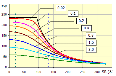
Comparison of individual theories (formulas) can be seen in the diagram of critical stress s dependent on slenderness rate of strut SR(l) Slenderness rate is a basic geometrical characteristic of the checked strut formulated by the formula:
where
Leff...Reduced (effective) strut length.
A...Profile area
Ix...Quadratic
moment of
inertia of profile
In the diagram, letters A,B and C determine areas of simple compression (A), nonelastic buckling (B) and elastic buckling (C).
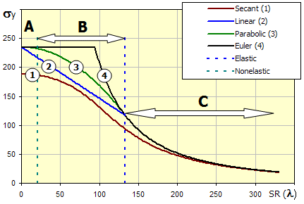
(The Secant formula has eccentricity degree set to 0.25 in this diagram)
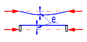
In cases when the force does not act directly in the strut axis (mounting imperfections) or if the strut is not accurately straight (inaccuracies in production, sag), the so-called Secant formula is used for calculation of stress in the extreme fibre of the profile.
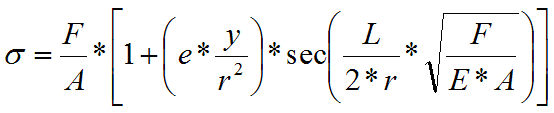
where
F...Force
A...Profile area
E...Modulus of elasticity in tension
r...Gyration radius
y...Extreme fibre distance
e...Deflection of origin of force or strut axis.
Equation in the brackets (e * y / r2) formulates the so-called eccentricity degree - m. With expected knowledge of m (estimation), the Secant formula is a very good substitution of the said empirical methods and is a basis for the whole range of suggested methods.
The diagram of critical stress s dependent on slenderness rate of the strut SR(l) shows curves for various values of eccentricity degree.
Calculation of optimum cross-section and strength check of slender struts includes the following steps:
During the check, set not only the cross-section type, but also dimensional values of the profile you are checking and check relevant safety coefficients.
In this paragraph, select units for calculation and the type of mounting of the strut stressed in buckling.
Select the desired system of calculation units in the list box. After switching over the units, all values will be changed immediately.
In the drop down menu, select the type of strut mounting according to the picture. The selection of the type of mounting leads to selection of a coefficient of reduced (effective) length that is used to multiply the real beam length to achieve so-called reduced (effective) beam length used in calculations. Line [1.4] specifies the theoretical value of the coefficient; line [1.5] the engineering value recommended to be used in the calculation.
| Indication | Strut mounting | Coef.(theor) | Coef.(pract) |
| A | Clamped - Clamped | 0.50 | 0.65 |
| B | Clamped - Hinged | 0.70 | 0.80 |
| C | Clamped - Guided | 1.00 | 1.20 |
| D | Hinged - Hinged | 1.00 | 1.00 |
| E | Clamped - Free end | 2.00 | 2.10 |
| F | Hinged - Guided | 2.00 | 2.00 |
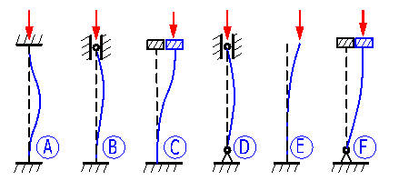
If the checkbox is checked, the value of the selected coefficient is put into the calculation, after the checkbox is unchecked, you can put in your own value of the coefficient of reduced (effective) strut length.
In this paragraph, select the type of beam, the respective static values and select a material.
Select the profile you want to use from the pop-up menu. Calculated profiles, selected rolled profiles according to ANSI/AISC and according to DIN are available. In the brackets following the name of the profile, there is a specification of the standard or indication of the calculated profile and a note on whether the value is a minimum or maximum of quadratic moment of inertia Ix.
After selection, the selected profile is shown in the illustration. In case you select a calculated profile, the input fields in which dimensions of the selected profile must be entered are shown to the right of the illustration. Follow the illustration when entering the dimensions.
If you select a standardized profile, the dimensions range is available in the drop down menu. Select a suitable profile dimension.
If the desired profile is not included in the database and calculated
profiles also do not fit, your own static values of the profile can be entered.
In such cases, switch over the selection to Yes and in the row [2.5,2.6 a
2.7] fill in the required values.
The lines give static values of the selected profile. You can set your custom values using the switch in line 2.4.
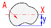
It is the distance of the extreme fibre from the profile axis which goes through the centre of gravity. This value is required for calculation using the "Secant" method.
In the pop-up list, select the material of the calculated beam. Structural steel with strength 36ksi and 50ksi is commonly available for ANSI profiles and structural steel EC 3, EN 10025; Fe 360; Fe 430; Fe 510 for DIN profiles .
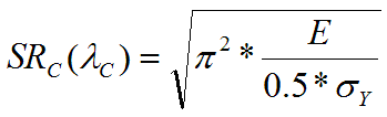
Limiting slenderness SRc (c) is an important parameter of a specific material, distinguishing the area of elastic and inelastic buckling as well as the use of relevant equations. It is, therefore, suitable to verify the parameter for the specific material. The recommended value is determined according to the equation:
Transfer the recommended value to proper cells by pressing the "<=" button
In this paragraph, you can design the beam profile able to transfer the desired load. You can also perform a check of a specific beam here.
For the design, set the beam length and force to be transferred by the beam [3.1, 3.2]. Select the safety coefficient and eccentricity degree [3.6, 3.7] and press the "Start" button. The program will select the minimum size of the selected type of profile or determine dimensions of the calculated profile. In case of the calculated profile, all profile dimensions are changed proportionally to the current values.
Rectangular profile with initial dimensions A=40mm, B=20mm will be adjusted e.g. to dimensions A=60mm, B=30mm after the calculation has been run
When checking a specific profile (dimensions have to be set in paragraph [2]), set beam length and force to be transferred by the beam [3.1, 3.2]. After setting the values, check the relevant safety coefficient [3.11, 3.15, 3.19, 3.27, 3.31]. A visual check can easily be performed in the diagram of critical stress on the slenderness rate. The current slenderness rate is marked with a red vertical line.
Set the actual length of the designed/checked strut.
Set the axial force affecting the strut.
The value is used in calculations. It is the actual length [3.1] multiplied by the reduced (effective) length coefficient [1.6].
The slenderness ratio of a specific beam determines which buckling zone the beam is in (simple compression, inflexible buckling, flexible buckling) and thus also the check method used for determination of the safety coefficient. The current slenderness ratio is marked with a vertical red line in the diagram.
After the “Start” button has been pressed, the dimensions of the profile to accommodate the set conditions is calculated, on the basis of input data (strut mounting and length, type of profile, material, load, safety). The design is performed using the "Secant" method.
The recommended values of the safety coefficient range from:
The degree of inaccuracy of a structure and load for the design of profile dimensions may be determined using this parameter. The parameter includes:
0.25...steel structures
0.15...general engineering
0.05...accurate rigid mountings
This formula is valid for the zone of elastic buckling – the current slenderness rate [3.4] must be bigger than the "Critical (limiting) slenderness rate" [2.13].
Valid in the zone of inelastic buckling – the current slenderness rate [3.4] must be smaller than the "Critical (limiting) slenderness rate" [2.13].
Valid in the zone of inelastic buckling – the current slenderness rate [3.4] must be smaller than the "Critical (limiting) slenderness rate" [2.13].
In cases when force does not act directly in the strut axis (mounting imperfections), or the strut is not accurately straight (manufacturing imperfections, sag), the so-called Secant formula is used to calculate stress in the extreme fibre of the profile.
Set eccentricity of a checked strut as shown in the picture. If the checkbox is checked, eccentricity is filled in automatically to achieve the eccentricity degree set in the drop down menu [3.23].
see [3.7]
Valid for short struts which are not subject to buckling.
The maximum axial load of the strut for individual above-mentioned methods is calculated for the set safety coefficient [3.33]. If the checkbox is checked, the safety coefficient from line [3.6] is used.
Information on setting of calculation parameters and setting of the language can be found in the document "Setting calculations, change the language".
General information on how to modify and extend calculation workbooks is mentioned in the document "Workbook (calculation) modifications".
^