Illustration picture of mechanical components 0 MITCalc is a collection of engineering, manufacturing, and technical calculations designed to make day-to-day engineering tasks significantly faster and easier. All calculations have been designed to guide users reliably, precisely, and quickly through numerous steps of designing mechanical components. The entire collection allows for solving of many technical problems and engineering calculations without the need for expert knowledge. 
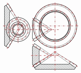
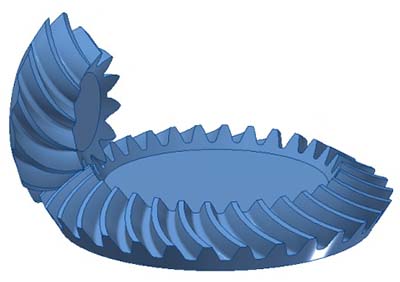
Included is support for many CAD systems with direct 2D and 3D output.

Are you a mechanical or design engineer, mechanical designer, or a college student? Do you need to work with a professional computer-aided system but you are unwilling to pay thousands of dollars for unnecessary complex or hard-to-learn solutions? If your answers are yes, you may benefit from checking out what MITCalc has to offer!

MITCalc offers both design and validating calculations for many common engineering tasks, including: Spur gear (External, Internal, Gear Rack), Bevel and Hypoid Gear, Worm Gear, Planetary Gearing, Timing Belt, V-Belt and Chain Drives, Brakes and Clutches, Bearings, Plain bearings, Springs, Beam, Buckling, Plates, Shells, Shaft, Power Screw and Ball Screw, Flywheels, Bolted Connection, Shaft Connection, Force Couplings of Shafts, Pins, Tolerances, Tolerance Analysis, Welded Connection, Fluid mechanics, Technical Formulas, and more. For a complete list of available calculations visit the Products page. MITCalc users also have access to several sets of material, comparison and decision tables, including a system for Administration of Completed Tasks. Both Imperial and Metric units are supported. All calculations can be processed according to ANSI, ISO, DIN, BS, CSN, Japanese, and other standards.

We are confident that MITCalc will become an essential tool for solving your everyday engineering tasks!
Illustration picture of mechanical components 1

Open System

The system is built upon Microsoft Excel and has been designed to allow customization. Every calculation is created as a separate Microsoft Excel Workbook sheet, which lets users to make further modifications, such as adding parameters, presetting parameters’ values, adjusting calculation coefficients, etc. Everything can be achieved without any coding skill with only basic knowledge of MS Excel. Furthermore, users can inter-link individual calculations or even include their own sheets. Simply put: One can easily adapt any solution to one’s specific needs.

Instant Productivity

The feature most appreciated by MITCalc users is that they do not have to learn it – most engineers already know how to use it. The familiar environment follows a well-established flow of procedures for solving standard technical tasks. When entering input values, defining edge conditions, and searching for the optimal solution, the user proceeds naturally from the top of a sheet toward the bottom. The no-frills user interface complemented by a comprehensive Online Help and the System of Expert Notes allows for full-speed productivity within minutes.

Open Design

Most of the calculations support a long list of established 2D CAD products and some calculation can even output a 3D model for selected parametric 3D CAD systems. One click on a button exports a 2D drawing or automatically inserts a 3D model of the calculated part or sub-assembly into a 3D CAD system. Like of the rest of MITCalc, this feature is also open to adapting to your needs. It is thus perfectly feasible to create a connection with 2D CAD, the definition of which is not part of the MITCalc application, create your own 2D drawing templates, which will be adjusted based on the calculated values when inserted or to extend the current options and properties of the built-in connections. Inserted 3D models are fully parametric, so you can further edit and change them directly in the CAD system.

Turning a solved calculation to either a 2D drawing or a 3D model is done in a matter of seconds with MITCalc!

Illustration picture of mechanical components 1

CAD Integration

The results of most calculations can be easily converted to a 2D drawing or 3D model of the designed part. For calculations that provide this option, you will find buttons for inserting the selected view or part into the selected CAD system.

Note: MITCalc is a certified developer for Autodesk®, Solid Edge®, and SolidWorks®

Hypoid Gear 2D drawing

2D CAD systems

In the calculation, simply select the target CAD system drawing (view) that you want to insert, and then the selected drawing in the correct scale and in the corresponding layer system is placed in the CAD system. You can also create a DXF file from the selected drawing (view). DXF file has a versatile use and you can insert it into 2D CAD and various graphic editors, or it can be easily used in 3D CAD systems as a basis for creating a 3D model.

Supported 2D CAD systems: AutoCAD®, AutoCAD LT®, Ashlar Graphite™, IntelliCAD®, TurboCAD®, BricsCAD®, ZWCAD™, ProgeCAD®, platform independent DXF file, and more.

Hypoid Gear 3D model

3D CAD systems

Integration to 3D CAD Systems is available as a separate module installed on top of the standard MITCalc package. The module includes parametric models and an interface for connecting Excel with the respective 3D CAD system. MITCalc thus becomes capable of generating assemblies consisting of either individual parts or groups of components (sub-assemblies). Generated components are fully associative (even you made additional modification into), which means that any part (a spring part or a belt gear sub-assembly, for example) needs to be inserted only once. Its dimensions will adapt automatically should the user make further changes to the calculation parameters later.

Supported 3D CAD systems: Autodesk Inventor®, SolidWorks®, Solid Edge®, and PTC Creo®