The calculation is designed for a geometrical design and strength check of common chain transmissions using roller chains.
The application solves the following tasks.
The application works with selected CAD systems and includes corresponding databases of roller chains. The calculations use data, procedures, algorithms and data from ANSI/ASME, ACA (American Chain Association) ISO, DIN, BS and JIS.
List of standards: ANSI/ASME B29.1M (Dec2001), ANSI/ASME B29.3, DIN 8187, DIN 8181, DIN 8181, DIN 8164, DIN 8150, ISO R606, ISO 1275, BS 228, JIS B1801, JIS B1803.
![]()
User interface.
![]()
Download.
![]()
Purchase, Price list.
Information on the syntax and control of the calculation can be found in the document "Control, structure and syntax of calculations".
Information on the purpose, use and control of the paragraph "Information on the project" can be found in the document "Information on the project".
A typical calculation / design of a roller chain transmission consists of the following steps:
In this paragraph, set calculation units, enter power parameters and set the loading mode and parameters for calculation of the transmission.
In the selective list, select the desired system of calculation units. All values will be recalculated immediately after switching to other units.
Enter the power demand of the driving wheel (Wheel1). The power of the driven wheel will be calculated according to the efficiency, which varies around 98% with transmissions using roller chains.
Enter the speed of the driving wheel and the desired speed of the driven wheel. The desired / actual transmission ratio is calculated [1.5].
These are calculated using the input speed and the number of teeth of the sprocket wheels.
The desired transmission ratio is calculated using the desired input and output speeds. The actual transmission
It is calculated using the actual speed [1.4] and the transferred power [1.2]
Select the type of driving machine which best fits your task.
Electric motors with low and medium starting torque.
Electric motors with higher starting torque, high-speed multi-cylinder engines (2 to 6 cylinders).
Internal combustion engines (low-speed, 1 and 2 cylinders).
Select the type of driven machine which best fits your task.
Office machines, dosing devices, wood-processing machines (light-duty operation), generators - small loading.
2-stage centrifugal compressors, conveyors for loose materials, blowers, wood-processing machines, mills, lathes, drilling machines, mixers.
Production machines, hydraulic presses, piston pumps, shapers, weaving looms, piston compressors, presses, crushing cylinders, conveyors for piece materials, shaking sieves, planning machines.
Eccentric presses, multi-stage piston compressors, fans, rolling trains, hammer mills, hoists, mining equipment, excavators, forklift trucks.
The calculation presupposes that the construction guarantees the required manner of lubrication depending on input conditions and results of the design in the row [4.10 a 4.11]. Select in this pop-up list which conditions the lubrication system will be operated in.
Set, using the switch, whether a chain with even or random number of links will be designed. In case of an odd number of links, it is necessary to use a special type of link for connection of the chain ends, which reduces the force for breaking the chain [3.12] by 20%. In general, it is therefore recommended to use chains with an even number of links.
The switch sets whether the sprocket wheel designed using the "Automatic design" will have an odd or random number of teeth. In view of wear and tear, it is advisable to use an odd number of teeth on sprocket wheels and an even number of links in the chain.
The automatic design goes through a list of all dimensions of the selected type of chain. The automatic design inserts from the list, successively for each dimension, the number of teeth for the smaller sprocket wheel from the range in the row [2.4]. The automatic design executes a complete design for each such alternative. The solutions which meet the desired input and output parameters are included in the table of results. A suitable solution with the lowest weight is selected after completion of the design. This solution is transferred to the paragraph of calculation [3].
With the automatic design proceed as follows.
The selective list includes the most frequently used types of roller and sleeve chains according to standards ANSI/AGMA, DIN, ISO, BS. The standard is given in parenthesis after the name of the chain.
- In case you do not know the axis distance or do not need to use a particular axis distance due to constructional reasons, select "Optimum" in the selective list and the Automatic design will use a recommended optimum axis distance in its calculations, i.e. 40-fold the spacing.
- If you know the axis distance, select "Manual" in the selective list and enter the desired value in the input field.
Here set the range for which the "Automatic design" will find a solution. Recommendations for numbers of teeth can be found in [3.3].
Pressing the button "Automatic design" initiates the Automatic design process. The displayed indicator shows the progress of the solution.
The results in the table of solutions can be re-classified at any time using another criterion selected in the pop-up list.
In case of Automatic design, the table includes all solutions which are not completely wrong. This provides a chance to select a solution with an insufficient index and then to make modifications manually. Immediately after selection of the solution in the list, the parameters of the solution are set in the paragraph of calculation [3].
The table of solutions includes the following values:
| Symbol | description |
| z1 | Number of teeth of the driving sprocket wheel |
| z2 | Number of teeth of the driven sprocket wheel |
| n2 | Speed of the driven sprocket wheel |
| i | Transmission ratio |
| A | Axis distance |
| Pp | The table power of the respective dimension of the chain for the given conditions |
| v | Peripheral speed of the chain |
| SD | Dynamic coefficient of safety against breaking |
| p | Calculated pressure in the chain joint |
| SP | Level of safety in the chain joint |
| Pp% | Utilization of the power potential of the chain in percent |
| m | Approximate total weight (both sprocket wheels + chain) |
The result of the Automatic design [2.5] or the result selected in the table of solutions [2.7] is set in the check calculation in this paragraph.
In the selective list, select the chain (size) which you wish to use for the calculation. The selective list is filled according to the selected type of chain [2.2]. The size specification of the chain (e.g. 20B, 100) is followed after the dash by the number of rows of the chain and the spacing is given in parenthesis [mm/inch].
Information on spacing of the selected chain and number of rows.
Enter the number of teeth of the driven wheel in this row. The green cell on the right shows the recommended (in parenthesis minimum) value of the driven wheel. The following practical recommendations exist for the selection.
Spacing diameter of both sprocket wheels.
Enter the desired axis distance. The recommended value, depending on spacing of the chain, is given in the green cell to the right of the input cell. The recommended axis distance is 40-fold the spacing of the selected chain.
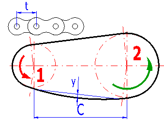
The actual axis distance depends on the number of teeth and the number of links of the chain. The design of the number of links of the chain is based on the desired axis distance and the number of teeth of the sprocket wheels. The number is then rounded to an integer (even integer) and the actual axis distance is calculated retrospectively. The green cell on the right gives the range of the minimum (constructionally possible) and maximum (recommended) axis distance.
The number of links of the chain necessary to achieve the desired axis distance is given in the green field on the right. If the check mark box is enabled, this value is used for the calculation. In case you wish to enter your own number of links of the chain, disable the check mark box and enter your own number in the cell on the left.
The cell gives the actual length of the chain.
The left cell gives the actual peripheral speed of the chain. The right green cell gives the maximum value of the peripheral speed for the given type and size of chain and entered input conditions. Exceeding the maximum peripheral speed is indicated by a change in color of the digit to red, critical excess by a change in color of the whole cell.
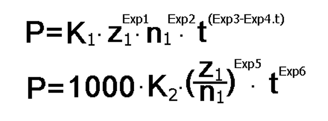
The design power is calculated using the desired power. The design power is modified (multiplied) by a series of coefficients [4.2 to 4.8]. It is then used for selection of the corresponding chain according to its table power. The table power is calculated using power equations. In case the design power is higher than the table power, the digit is red. If it is exceeded 1.5-times, the background of the cell is red.
Power equations are used to calculate the table power. These equations include a series of coefficients (the sheet "Tables", table "Chain types - Main table" columns 6,8,10 to 16) which affect the calculated power. For the purpose of estimating these coefficients with chains from a particular producer, we can send an application "Editor of power equations" to registered users upon request.
Tensile force appears in the chain on the basis of the transferred power, speed and diameter of sprocket wheels. This force must be taken as a basis for the design (check) of shafts and bearings. The centrifugal force is effective at higher speeds of the chain and its sum with the tensile force gives the resulting force acting on the chain.
It is the force when the chain breaks if this force is reached. It is a table value. The force on the chain is a sum of tensile and centrifugal forces.
The actual value of the designed chain is on the left. The value which is recommended for common conditions of the designed solution is on the right. A lower value than the recommended one is indicated by a red number; exceeding the critical value (=5) is indicated by a change in the color of the cell.
The same is also applicable for dynamic coefficient of safety as for static coefficient of safety.
The actual value of pressure of the designed chain is on the left, the maximum value is on the right. The maximum value should not be exceeded. The red digit indicates exceeding of the maximum permitted value. The red highlighted maximum permitted value in the green cell indicates that the operational field of the chain is outside the recommended values.
It is a ratio between the calculated and permitted pressures in the chain joint. The value of this coefficient should be higher than 1. Any lower value is indicated by a red digit.
The total weight is the sum of estimated weights of both sprocket wheels and the chain. Steel is considered as the default material for wheels. The weight of the chain is calculated exactly according to the table values.
Despite the fact that the total weight is approximate only, it is a very good optimizing parameter which should be taken into account with the design.
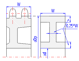
The weight of the sprocket wheels is calculated according to the simplified illustration on the right.
This paragraph gives coefficients used for calculating the "Design power" [3.10] and other parameters of the designed transmission
The table power is mostly specified in the form of power diagrams for the below-mentioned standard conditions. Service life of the chain of 15,000 hours is given for these conditions.
Therefore, it is necessary to correct the desired transmitted power by a series of parameters which respect the conditions of a real operation.
The coefficient of the number of teeth respects another number of teeth of a wheel smaller than the standard one. Leave the preset value "K1=1.0" for this calculation. The effect of teeth is already included in the calculation of the table power [3.10] according to the power equations which are included in the database of chains.
This coefficient respects the effects of a transmission ration other than 1:3.
The coefficient of a shock respects loads other than standard quiet shock-free ones. The coefficient is inserted according to the presetting in paragraph [1] in the row [1.7, 1.8].
The coefficient respects a distance of the axes other than the optimum one
The manner and quality of lubrication significantly affects the service life of the chain. The coefficient, therefore, also respects calculation of the "Design power" according to the preset quality of lubrication.
For usual temperatures it is K6=1.0. In case of significantly higher (lower) temperatures, consult the producer of the chain. The table can be used if the data are not available.
| Temperature | ||
| up to 80 °C up to 175 °F |
80 to 150 °C 175 to 300 °F |
150 to 250 °C 300 to 480 °F |
| 1.0 | 1.1 | 1.2 |
Respects daily utilization of the transmission. For this calculation it is K7=1.0. Consult the coefficient with the producer of the chain. The table can be used if the data are not available.
| Daily utilization of the transmission [hours] | ||
| 8 | 16 | 24 |
| 1.0 | 1.1 | 1.2 |
Calculation of the "design power" is different according to ANSI/ASME B29.1M, different according to ISO 10823 (DIN 8195) and recommendations of various producers are also different. The calculation (or coefficients resp.) in this workbook can be switched between ANSI / ISO, or it is possible to select your own values according to recommendations of the producers.
The manner of lubrication is recommended with regards to the speed of the chain and its spacing.
Lubrication very considerably affects the service life and quality of the chain transmission. Therefore, pay increase attention to the lubrication. The red
colored text indicates an inadmissible combination of the recommended manner of lubrication and its quality [1.9].
This gives the recommended maximum slackness of the chain in case the wheels are parallel.
see [4.14]
Two types of dimensions are given in this paragraph.
Despite the fact that it is advisable to consult the manner and quality of lubrication with the producer of the chain, an orientation table of recommended oils for various operational temperatures is given here.
|
|
|
||||
|
ANSI/AGMA |
ISO/DIN |
||||
| 50 and lower | 10A/B and lower | ||||
| 12A/B-16A/B | |||||
| 20A/B | |||||
| 120 and higher | 24A/B and higher | ||||
Information on options of 2D and 3D graphic outputs and information on cooperation with 2D and 3D CAD systems can be found in the document "Graphic output, CAD systems".
Information on setting of calculation parameters and setting of the language can be found in the document "Setting calculations, change the language".
General information on how to modify and extend calculation workbooks is mentioned in the document "Workbook (calculation) modifications".
All parameters of available chains are given in the sheet "Tables", which is accessible by clicking on the tab with the name of the sheet in the lower part of the workbook. The basic data for the calculation are saved in the table "Chain types - Main table", where each row corresponds to one chain type. The columns of the table are provided with the respective descriptions for simple orientation. The data referring to a particular size of the chain are saved in the following tables.
For the purpose of estimations of coefficients Exp1...Exp6 with chains from specific producers, we can send an application "Editor of power equations" to the registered users upon request.
^