This program is designed to solve common thermomechanics and heat transfer problems that engineers frequently encounter.
The program addresses the following areas:
1. Energy: Heating and cooling, phase change, fuel calorific value
2. Ideal Gas: State and state change, thermodynamic system
3. Heat Transfer through Composite Walls: Conduction, radiation, convection
4. Solutions for Finned Walls and Tube Bundles
5. Longitudinal Temperature Change in Piping. Temperature change and cooling time in tanks
6. Heat Exchangers
7. Heat Transfer by Radiation
8. Solar Radiation Power: Time, position, location, environment, surface orientation, etc.
9. Data Preparation for the "Solver" Add-in
The calculations include hundreds of predefined materials, liquids, and gases, a periodic table of elements, unit conversions, and more. A number of solved examples are also available.
The calculations use data, procedures, algorithms, and information from professional literature, standards, and company catalogs.
[01] YUNUS A. ÇENGEL, AFSHIN J. GHAJAR: Heat and Mass Transfer: Fundamentals
& Applications, 5th Edition, McGraw-Hill Education.
[02] YUNUS A. ÇENGEL: Heat Transfer a Practical Approach, Second Edition.
[03] MORAN, M.J., SHAPIO, H.N.: Fundamentals of engineering thermodynamics. 8th
Edition New York: John Wiley a sons, 1990.
[04] DEWITT, BERGMAN, LAVINE: Fundamentals of Heat and Mass Transfer 6th Edition
[05] WARREN M.ROHSENOW, JAMES R.HARTNETT, YOUNG I.CHO: Handbook of Heat
Transfer, 3th Edition, McGraw-Hill
[06] SCHLUNDER, BELL, HEWITT, SPALDING: Heat Exchanger
Design Handbook, VDI-Verlag GmbH, 1983.
[07] LOIS THEODORE: Heat Transfer Applications for the
Practicing Engineer, John Wiley & Sons, Inc., 2011.
[08] MYER KUTZ: Heat-Transfer Calculations,
McGraw-Hill
[09] HOLMAN, J.P.: Heat Transfer, 10th. Edition, New
York: McGraw-Hill
[10] HOLMAN, J.P. Thermodynamics. 4th. New York:
McGraw-Hill Book Company, 1988. 780 s. ISBN 0-07-029633-2.
[11] MOHAMED M. EL-AWAD: Optimisation Analyses of
Fluid- Thermal Systems Using Excel,
[12] FRANK KREITH, RAJ MANGLIK, MARK BOHN: Principles
of Heat Transfer, Cengage Learning, Inc., 2011
[13] HORÁK VLADIMÍR, STŘEDA IVO: Mechanika tekutin
- Termomechanika, Strojírenská příručka, Scientia sro.
[14] RANEVI,K. Termodynamické tabulky. 1.vyd.
Bratislava: ALFA 1984. 313s. [L5] HAEK, P. Tabulky pro tepelnou techniku. 1
.vyd. VB Ostrava, 1980, 247 s.
[15] SAZIMA,M., KMON1OEK,V., SCHNELER,J. Teplo. 1.vyd.
Praha: SNTL, 1989. 588 s. Technický průvodce. ISBN 80-03-00043-2.
[16] M.A.MICHEJEV: Základy sdílení tepla, Průmyslové
vydavatelství, 1952
[17] PETRAK,J., DVOAK, Z., KLAZAR, L., SYNEK, V.
Chiadivo R134a, (1.vyd.) VUT, 1993. 72s.
[18] MIROSLAV JÍLEK, ZDENĚK RANDA: Termomechanika -
sbírka příkladů, ČVUT, 2004
Information on the syntax and control of the calculation can be found in the document "Control, structure and syntax of calculations".
Information on the purpose, use and control of the paragraph "Information on the project" can be found in the document "Information on the project".
E = m * ΔT
* Cp
E ... Energy [J]
m ... Mass [kg]
ΔT
... Temperature change [K]
Cp ... Specific heat capacity [J/kg/K]
EM
= m * CpM
* 1000
EB
= m * CpB
* 1000
EM, EB
... Energy [J]
CpM
... Specific heat capacity of melting [kJ/kg]
CpB
... Specific heat capacity of boiling [kJ/kg]
E = m * HHV
* (η / 100) * 1000000
E ... Energy [J]
m ... Mass of fuel burned [kg]
HHV
... Heat of combustion [MJ/kg]
η ... Combustion efficiency [%]
The state of a thermodynamic system
is characterized by state variables. The relationship between these state
variables is defined by equations of state.

A ... An example of a simple thermodynamic system, the ideal gas, follows the
equation: p*V=m*r*T.
B ... Reversible processes can be described more generally as polytropic
processes, where the heat capacity of a closed system remains constant. In a polytropic
process, all state variables (p,V,T)
generally change. For a
polytropic process in an ideal
gas, the equation p*V^n = const. applies. The p-V and T-s diagrams show the
change curves for various values of n.
C ... Carnot
Cycle. An example of an ideal heat engine that consists of two isothermal and
two adiabatic processes.
D ... Curves of fundamental reversible state changes.
p * V = m * r * T
r = R / M
M = m / N
p ... Absolute pressure [Pa]
V ... Volume [m^3]
m ... Mass [kg]
T ... Temperature [°K]
R ... Universal gas constant R=8314.46261815324 [J/kmol/K]
M ... Molar mass of gas [kg/kmol]
(air 28.966 kg/kmol)
N ... Amount of substance [kmol]
r ... Specific gas constant [J/kg/K] (air 287.0427 J/kg/K)
u = u0 + cv * (T - T0) [J/kg]
Δu = cv * (T2 - T1) [J/kg]
h = h0 + cp * (T - T0) [J/kg]
Δh = cp * (T2 - T1) [J/kg]
ds
= s2 - s1 = cp * Ln(T2/T1) - r * Ln(p2 / p1)
ds
= s2 - s1 = cv
* Ln(T2/T1) + r * Ln(v2 / v1)
cp - cv
= r
cp ... Specific heat capacity - constant pressure [J/kg/K]
cv
... Specific heat capacity - constant volume [J/kg/K]
κ = cp / cv
cv
= r / (κ - 1)
cp = κ * cv
p1 * V1 = p2 * V2
V1 / V2 = T1 / T2
Reversible processes can be considered as more general polytropic processes for which:
p * V^n = constant
T2 / T1 = (V1 / V2)^(n-1) = (p2 / p1)^((n-1)/n)
n . .. Polytropically exponent [~]
For selected values of n then:
n=0 , p=const, Isobaric, (dp=0,
wt=0, q=Δh,
w=Δh-Δu)
n=1 , T=const, Isothermic,
(dT=0, Δu=Δh=0,
q=w=wt)
n=κ , s=const, Isoentropic,
(ds=0,
q=0, w=-Δu,
wt=-Δh)
n=∞ , v=const, Isochoric, (dv=0,
w=0, q=Δu,
wt=Δu-Δh)
n = ln(p2 / p1) / (ln(p2 / p1) -
ln(T2 / T1))
n = (ln(V2 / V1) - ln(T2 / T1)) / ln(V2 / V1)
q = cn
* (T2 - T1) [J/kg]
cn
= cv
* (n - κ) / (n - 1)
cn
... Polytropic
specific heat capacity [J/kg/K]
w = q - Δu [J/kg]
wt = q - Δh = n * w [J/kg]
Calculating the parameters of a gas
that is introduced by mixing two parts with different parameters p,V,T.
m = m1 + m2
p = m / M * R * T / V
V = V1 + V2
T = (m1 * T1 + m2 * T2) / (m1 + m2)
This is a frequently encountered problem in mechanical engineering and other related fields. While this issue can certainly be addressed using appropriate simulation software, a simple calculation based on fundamental physical relationships is often sufficient for initial estimations and a significant portion of these tasks.
Heat transfer is categorized into conduction, convection, and radiation. The relevant equations are provided below.
The following equations are used for calculations involving composite plane, cylindrical, and spherical walls (up to 10 layers).

r(i)=D(i)/2
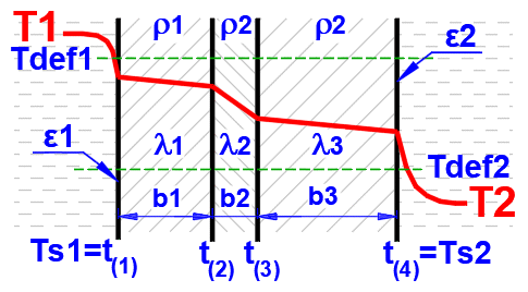
q' = -λ * ΔT
qp'
= (t(1) - t(n+1)) / Rp
qp'
= (t(1) - t(n+1)) / Σ (b(i)
/ λ(i))
..... [i=1...n]
R = Rp = Σ (b(i) / λ(i)) ..... [i=1...n]
qc' = (t(1) - t(n+1)) / Rc
qc' = (t(1) - t(n+1)) / (1/(2 * 3.14) * Σ ((1/λ(i))
* ln(r(i+1)/r(i))))
..... [i=1...n]
Rc = (1 / (2 * 3.14159) * Σ ((1/λ(i)) * ln(r(i+1)/r(i)))) ..... [i=1...n]
R = Rc * (2 * 3.14159 * r(1))
qs'
= (t(1) - t(n+1)) / Rs
qs'
= (t(1) - t(n+1))
Heat transfer occurs within the boundary layer near a surface, which forms due to temperature differences. The heat transfer itself depends on a variety of parameters (fluid properties, flow type, surface geometry, etc.).
For both forced convection (where the medium is driven) and free convection, numerous equations based on measurements and approximations are available (see literature). The most crucial and frequently used ones are employed in this calculation. These equations, their valid ranges, and corresponding graphs are provided below. The graphs utilize dimensional values that represent typical applications. For comparative purposes, air and water, as the most common working fluids, are chosen for the graphs.
For the graphs, the following units are used: Temperature [°C], Dimensions [mm].
Most of the relationships used are empirical equations, with results expressed through dependencies of dimensionless similarity criteria.
Grashofer number Gr = 9.81 * L * β * abs(T -
Ts) / ν
Nusselt number Nu = hc * L /
λ
Prandtl number Pr = (µ / Rho) / (λ
/ (Cp * Rho))
Rayleigh number Ra = Gr * Pr
Reynolds number
Re = (L * V) /
ν
Generally, the following formula is used:
hc = (Nu * λ) / L

01a.
Flow in tube - circle
(D,L): [Tdef = (T+Ts)/2, 0.1<Re<1e7] ...
(Strojírenská příručka, Graetz)
hc = (Nu *
λ) / D
Nu = (3.65 + (0.0668 * Re * Pr * (D/L)) / (1 + 0.045 * (Re * Pr *
(D/L))^(2/3))) * (μ / μs)^0.14 ..... [Re<2300]
Nu = 21 * (Pr * (D/L))^0.33 * (Re/2300)^(LOG(L/D)) ..... [Re*Pr*(D/L)>12, Pr>0.5,
L/D>30, 2300<Re<5000]
Nu = 3.66 * (Re/2300)^(2.3 + LOG(Pr) ..... [Re*Pr*(D/L)<12, Pr>0.5, L/D>30,
2300<Re<5000]
Nu = E * (0.023 * Pr^H * Re^0.8) * K ..... [0.5<Ts/Tdef<1 (°K),
1e4<Re<2e6]
Nu = E * (0.023 * Pr^H * Re^0.8) * K ..... [1<Ts/Tdef<3.5 (°K),
1e4<Re<2e6]
Coefficient H
H = 0.4 ..... T<Ts
H = 0.3 ..... T>Ts
Coefficient K
K = 1.27 - 0.27 * (Ts/Tdef) ..... [0.5<Ts/Tdef<1, Ts(°K),
T(°K)]
K = (Ts/Tdef)^(-0.55) ..... [1<Ts/Tdef<3.5, Ts(°K),
T(°K)]
Coefficient E
| ▼ Re... L/D ► | 1 | 2 | 5 | 10 | 15 | 20 | 30 | 40 | 50 | 1000 |
| 1.00E+04 | 1.65 | 1.50 | 1.34 | 1.23 | 1.17 | 1.13 | 1.07 | 1.03 | 1.00 | 1.00 |
| 2.00E+04 | 1.51 | 1.40 | 1.27 | 1.18 | 1.13 | 1.10 | 1.05 | 1.02 | 1.00 | 1.00 |
| 5.00E+04 | 1.34 | 1.27 | 1.18 | 1.13 | 1.10 | 1.08 | 1.04 | 1.02 | 1.00 | 1.00 |
| 1.00E+05 | 1.28 | 1.22 | 1.15 | 1.10 | 1.08 | 1.05 | 1.03 | 1.02 | 1.00 | 1.00 |
| 1.00E+06 | 1.14 | 1.11 | 1.08 | 1.05 | 1.04 | 1.03 | 1.02 | 1.01 | 1.00 | 1.00 |
| 1.00E+12 | 1.00 | 1.00 | 1.00 | 1.00 | 1.00 | 1.00 | 1.00 | 1.00 | 1.00 | 1.00 |
01b. Flow in tube - circle
(D,L): [Tdef = (T+Ts)/2, 0.1<Re<1e7] ... (Principles of Heat Transfer
7th. edtion)
hc = (Nu *
λ) / D
Nu = (3.65 + (0.0668 * Re * Pr * (D/L)) / (1 + 0.045 * (Re * Pr *
(D/L))^(2/3))) * (μ / μs)^0.14 ..... [Re<2100]
Nu = 0.023
* Re^0.8
*
Pr^H ..... [0.5<Pr<160,
6000<Re<1e7, L/D<60]
Coefficient H
H = 0.4 .... T<Ts
H = 0.3 .... T>Ts
01c.
Flow in tube - circle
(D,L): [Tdef = (T+Ts)/2, 0.1<Re<1e7] ...
(Heat Transfer Applications for the Practicing Engineer)
hc = (Nu *
λ) / D
Nu = 1.86 * (Re * Pr * (D / L))^(1/3) * (μ / μs)^0.14
..... [Re<2100]
Nu =0.027 * Re^0.8 * Pr^(1/3) *
(μ / μs)^0.14 ..... [0.5
< Pr < 10000,
Re>2100]
Re-Nu graphs for Air and Water (T ... [°C], D,Dh,L ... [mm])
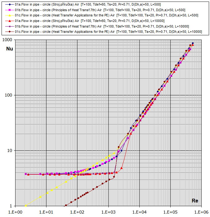
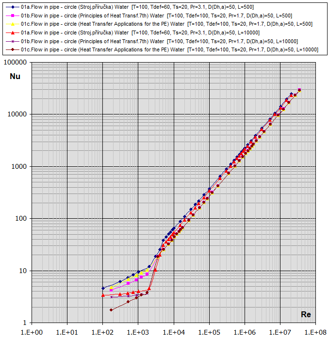

02.
Flow in tube - rectangle (a,b) Dh = 2 * a * b / (a + b): [Tdef =
(T+Ts)/2, 0.1<Re<1e7] ...
(Strojírenská příručka)
03. Flow in tube - square (a) Dh = a: [Tdef = (T+Ts)/2, 0.1<Re<1e7]
...
(Strojírenská příručka)
04. Flow in tube - hexagon (a) Dh = a: [Tdef = (T+Ts)/2, 0.1<Re<1e7] ...
(Strojírenská příručka)
06. Flow in tube - general profile (Ac,P) Dh = 4 * Ac / P: [Tdef = (T+Ts)/2,
0.1<Re<1e7] ...
(Strojírenská příručka)
hc = (Nu *
λ) / Dh
Nu = (3.65 + (0.0668 * Re * Pr * (Dh/L)) / (1 + 0.045 * (Re * Pr *
(Dh/L))^(2/3))) * (μ / μs)^0.14 .... [Re<2300]
Nu = 0.037*(1 + (Dh/L)^(2/3)) * (Re^0.75 - 180) * Pr^0.42 .... [Re>2300]
05. Flow in tube - intermediate circle (d1,d2) Dh = d1 - d2: [Tdef = (T+Ts)/2, 0.1<Re<1e7] ... (Gnielinski)
hc = (Nu * λ) / Dh
Laminar flow [Re<2300] by approximation from the table:
| Diameter ratio | NuL1 | NuL2 |
| d2/d1 | (inside) | (outside) |
| 0.00 (tube) | - | 4.36 |
| 0.05 | 17.46 | 4.79 |
| 0.1 | 11.56 | 4.86 |
| 0.25 | 8.24 | 5.1 |
| 0.5 | 6.49 | 5.47 |
| 1.00 (planar slot) | 5.39 | 5.39 |
Turbulent flow [Re>4000]:
For the inner circle
NuT1=(0.86*(y)^(-0.16)) * NuS1
For the outer circle
NuT2=(1 - ((1 - 0.86*(y)^0.16) / (3 * (y)))) * NuS2
y = d2 / d1 ... Ratio of diameters
NuS = ((f / 8) * (Re - 1000) * Pr) / (1 + 12.7 * (f / 8)^0.5 * (Pr^(2/3) - 1))
f = (1.82 * log(Re) - 1.64)^(-2)
Flow in the transition region (2300<Re<4000):
Linear interpolation from NuL
and NuT
NuP = (1 - (Re - 2300)/1700) * NuL + ((Re - 2300)/1700) * NuT

fcoeff ... Oblique tube wrapping
| φ | 0° | 10° | 20° | 30° | 40° | 50° | 60° | 70° |
| fcoeff | 1.00 | 1.00 | 0.99 | 0.95 | 0.86 | 0.75 | 0.63 | 0.50 |
07a.
Flow across a tube - cylinder (D): [Tdef = (T+Ts)/2, 0.5<Pr<1e3, 0.4<Re<4e5] ...
(Strojírenská příručka)
hc = (Nu *
λ) / D
* fcoeff
Nu =1.11 * K * Re^m * Pr^0.31
Nu =1.11 * K * Re^m * Pr^0.31 * (0.785 * (Ts/T)^(m/4) ..... for Gas
| Re | K | m |
| 0.4<Re<4 | 0.891 | 0.33 |
| 4<Re<40 | 0.821 | 0.385 |
| 40<Re<4e3 | 0.615 | 0.466 |
| 4e3<Re<4e4 | 0.174 | 0.618 |
| 4e4<Re<4e5 | 0.0239 | 0.805 |
07b.
Flow across a tube - cylinder (D): [Tdef =
T, 0.5<Pr<1e3,
0<Re<1e6] ...
(Principles of Heat Transfer
7th. edtion)
hc = (Nu *
λ) / D
* fcoeff
Nu =C * Re^m * Pr^n * (Pr/Prs)^0.25
n = 0.37 [Pr<10]
n= 0.36 [Pr>10]
| Re | C | m |
| Re<40 | 0.75 | 0.4 |
| 40<Re<1e3 | 0.51 | 0.5 |
| 1e3<Re<2e5 | 0.26 | 0.6 |
| 2e5<Re<1e6 | 0.076 | 0.7 |
07c.
Flow across a tube - cylinder
(D): [Tdef = (T+Ts)/2, 0.5<Pr<1e3, 0.04<Re<4e5] ...
(Heat Transfer Applications
for the Practicing Engineer)
hc = (Nu *
λ) / D
* fcoeff
Nu = C * Re^m * Pr^0.3333
| Re | C | m |
| 0.04<Re<4 | 0.989 | 0.33 |
| 4<Re<40 | 0.911 | 0.385 |
| 40<Re<4e3 | 0.683 | 0.466 |
| 4e3<Re<4e4 | 0.193 | 0.618 |
| 4e4<Re<4e5 | 0.027 | 0.805 |
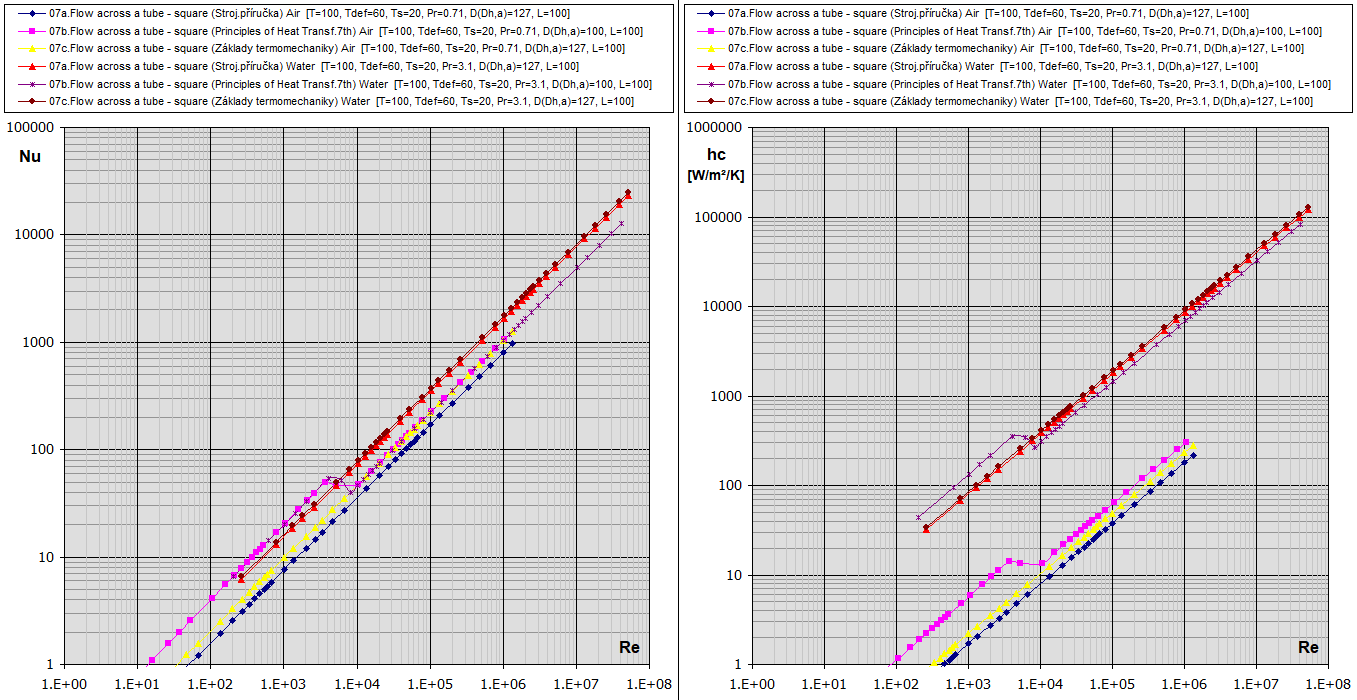
Re-Nu graphs for Air and Water
(Temp in °C, Dimensions in mm)
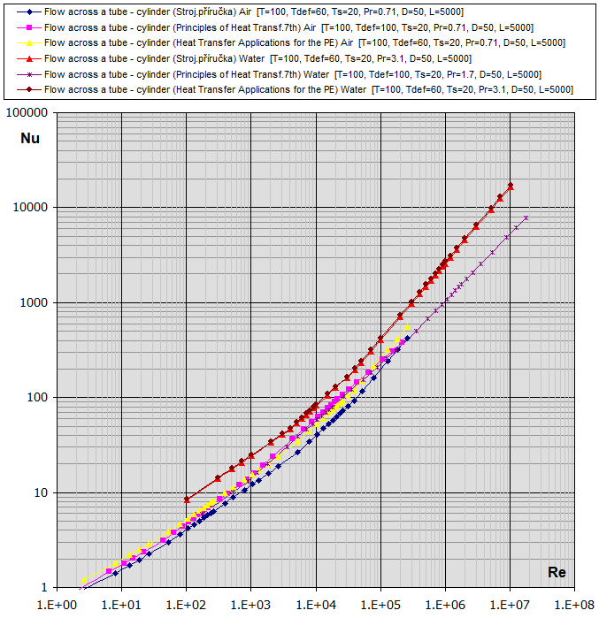

fcoeff ... Oblique tube wrapping
| φ | 0° | 10° | 20° | 30° | 40° | 50° | 60° | 70° |
| fcoeff | 1.00 | 1.00 | 0.99 | 0.95 | 0.86 | 0.75 | 0.63 | 0.50 |
08a. Flow across a tube - square (a):
[Tdef = (T+Ts)/2, 5e3<Re<1e5,
0.5<Pr<1e3, 20<T<1000C] ...
(Strojírenská příručka)
Dh =4
* a / 3.14
Re = (Dh * v) / KinVis
hc = (Nu *
λ) / Dh
* fcoeff
Nu =1.11 *
0.0921 * Re^0.675 * Pr^0.31
Nu =1.11 * 0.0921 * Re^0.675 * Pr^0.31 * (0.785 * (Ts/T)^(0.675/4) ..... for Gas
08b. Flow across a tube - square (a):
[Tdef = T, 2.5e3<Re<1e5,
0.6<Pr<0.85] ...
(Principles of Heat Transfer
7th. edtion)
Dh = a
Re =(a * v) / KinVis
hc = (Nu *
λ)
/ a
* fcoeff
Nu =
0.16
*
Re^0.699
... [2.5e3<Re<8e3]
Nu = 0.092 * Re^0.675 ... [5e3<Re<1e5]
08c. Flow across a tube - rectangle (a,b):
[Tdef
= (T+Ts)/2, 2.5e3<Re<1e5, 0.5<Pr<1e3,
0.5<a/b<1] ...
(Principles of Heat Transfer
7th. edtion)
Dh =2
* (a + b) / 3.14
Re = (Dh * v) / KinVis
hc = (Nu *
λ)
/ a
* fcoeff
Nu = 0.104 *
Pr^0.35 *
Re^0.675
..... [a/b=1]
Nu = 0.264
* Pr^0.35 *
Re^0.66
...... [a/b=0.5]
Re-Nu-hc graphs for Air and Water (Temp in °C, Dimensions in mm)
09a. Flow across a tube - square (a):
[Tdef = (T+Ts)/2, 5e3<Re<1e5,
0.5<Pr<1e3, 20<T<1000C] ...
(Strojírenská příručka)
Dh =4 * a / 3.14
Re = (Dh * v) / KinVis
hc = (Nu *
λ) / Dh
* fcoeff
Nu =1.11 *
0.222 * Re^0.588 * Pr^0.31
Nu =1.11 * 0.222 * Re^0.588
* Pr^0.31 * (0.785 * (Ts/T)^(0.588/4) ..... for Gas
09b. Flow
across a tube - square (a):
[Tdef = T, 2.5e3<Re<1e5,
0.6<Pr<0.85] ...
(Principles of Heat Transfer
7th. edtion)
x = (2 *
a^2)^0.5
Re =(x *
v) / KinVis
hc = (Nu *
λ)
/ x
* fcoeff
Nu =
0.261*
Re^0.624 ... [2.5e3<Re<7.5e3]
Nu = 0.222 * Re^0.588 ... [5e3<Re<1e5]
10a. Flow
across a tube - hexagon (a):
[Tdef = (T+Ts)/2, 5e3<Re<1e5,
0.5<Pr<1e3, 20<T<1000C] ...
(Strojírenská příručka)
Dh =6 * a / (3^0.5) / 3.14
Re = (Dh * v) / KinVis
hc = (Nu *
λ) / Dh
* fcoeff
Nu =1.11 *
0.138 * Re^0.638 * Pr^0.31
Nu =1.11 * 0.138 * Re^0.638
* Pr^0.31 * (0.785 * (Ts/T)^(0.638/4) ..... for Gas
10b. Flow across a tube -
hexagon (a):
[Tdef = (T+Ts)/2,
5e3<Re<1e5,
0.6<Pr<0.85] ... (Principles of Heat
Transfer
7th. edtion)
Re =(a *
v) / KinVis
hc = (Nu *
λ)
/ a
* fcoeff
Nu = 0.138 * Re^0.638
11a.
Flow across a tube - hexagon (a):
[Tdef = (T+Ts)/2, 5e3<Re<1.95e4,
0.5<Pr<1e3, 20<T<1000C] ...
(Strojírenská příručka)
Dh =6 * a / (3^0.5) / 3.14
Re = (Dh * v) / KinVis
hc = (Nu * λ) / Dh
* fcoeff
Nu =1.11 *
0.144
* Re^0.638 * Pr^0.31
Nu =1.11 * 0.144 * Re^0.638
* Pr^0.31 * (0.785 * (Ts/T)^(0.638/4) ..... for Gas
11b.
Flow across a tube - hexagon (a):
[Tdef = (T+Ts)/2, 5e3<Re<1e5, ,
0.6<Pr<0.85] ... (Principles of Heat
Transfer
7th. edtion)
x = 2 * a /
(3^0.5)
Re =(x *
v) / KinVis
hc = (Nu *
λ)
/ x
* fcoeff
Nu =
0.144
*
Re^0.638 ... [5e3<Re<1.95e4]
Nu = 0.035 * Re^0.782 ... [1.95e4<Re<1e5]
12. Flow across a
sphere (D):
[Tdef = T, 3.5<Re<2e5,
0.7<Pr<380] ... (Principles
of Heat Transfer
7th. edtion)
hc = (Nu *
λ)
/ D * fcoeff
Nu =2 + (0.4 *
Re^0.5 + 0.06 * Re^(0.67)) * Pr^0.4 * (μ
/ μs)^0.25 ...
[3.5<Re<76000]
Nu =2 + (Re / 4 + 0.0003 *Re2^1.6)^0.5 ... [76000<Re<2e5]
13.
Flow across a plate φ=90° (a): [Tdef
= (T+Ts)/2, Re<1e7, 0.6<Pr<60]
... (Heat
Transfer Applications for the Practicing Engineer)
Re =(a *
v) / KinVis
hc = (Nu *
λ)
/ a
* fcoeff
Nu =
0.644
*
Re^0.5 *
Pr^0.333
... [Re<5e5,
0.6<Pr<50]
Nu = 0.037 * Re^0.8 * Pr^0.333 ... [5e5<Re<1e7,
0.6<Pr<60]

A.
Flow across Tube Banks (D,
ST, SL, n): [Tdef = (T+Ts)/2, 0.7<Pr<500, 10<Re<200000]
...
(Principles of Heat Transfer
7th. edtion)
hc = (Nu *
λ) / D * A
Nu = 0.8 * Re^0.4 * Pr^0.36 * (Pr/Prs)^0.25 [10<Re<1000]
Nu = 0.27 * Re^0.63 * Pr^0.36 * (Pr/Prs)^0.25 [1000<Re<2e5, ST/SL>0.7]
Nu = 0.021 * Re^0.84 * Pr^0.36 * (Pr/Prs)^0.25 [2e5<Re]
|
n |
1 |
2 |
3 |
4 |
5 |
6 |
7 |
8 |
9 |
10 |
|
Coeff A |
0.68 |
0.75 |
0.83 |
0.89 |
0.92 |
0.95 |
0.97 |
0.98 |
0.99 |
1.00 |
|
Coeff B |
0.64 |
0.80 |
0.87 |
0.90 |
0.92 |
0.94 |
0.96 |
0.98 |
0.99 |
1.00 |
B.
Flow across Tube Banks (D,
ST, SL, n): [Tdef = (T+Ts)/2, 0.7<Pr<500, 10<Re<200000]
...
(Principles of Heat Transfer
7th. edtion)
hc = (Nu *
λ) / D * B
Nu = 0.9 * Re^0.4 * Pr^0.36 * (Pr/Prs)^0.25 [10<Re<1000]
Nu = 0.35 * (ST/SL)^0.2 * Re^0.6 * Pr^0.36 * (Pr/Prs)^0.25 [(ST/SL)<2,
1000<Re<2e5]
Nu = 0.4 * Re^0.6 * Pr^0.36 * (Pr/Prs)^0.25 [(ST/SL)>2, 1000<Re<2e5]
Nu = 0.022 * Re^0.84 * Pr^0.36 * (Pr/Prs)^0.25 [Pr>1, 2e5<Re]
Nu = 0.019 * Re^0.84 [Pr=0.7, 2e5<Re]

14-15. Vertical plate or
cylinder
(L): [Tdef = (T+Ts)/2, 1e3 < Ra < 1e13]
... (Heat Transfer Applications for the Practicing Engineer)
hc = (Nu *
λ)
/ L
Nu = 0.59 * Ra^0.25 [1e4<Ra<1e9]
Nu = 0.10 * Ra^0.333 [1e9<Ra<1e13]
16. Tilted plate
(L):
[0°<φ<89.9°, Tdef = (T+Ts)/2, 1e3 < Ra < 1e13]
...
(Principles of Heat Transfer
7th. edtion)
hc = (Nu *
λ)
/ L
Nu = 0.59 * (Ra*cos(φ))^0.25
[1e4<Ra<1e9]
Nu = 0.10 * (Ra*cos(φ))^0.333
[1e9<Ra<1e13]
17.
Plate - upper surface (smaller of the
AxB dimensions): [Tdef = (T+Ts)/2, 2e4 < Ra < 1e11]
... (Heat Transfer Applications for the Practicing Engineer)
hc = (Nu *
λ)
/ L
Ts > T
Nu = 0.54 * Ra^0.25 [2e4 < Ra < 8e6]
Nu = 0.15 * Ra^0.333 [8e6 < Ra < 1e11]
Ts < T
Nu = 0.58 * Ra^0.2 [8e6 < Ra < 1e11]
17.
Plate - bottom surface (smaller of the
AxB dimensions): [Tdef = (T+Ts)/2, 2e4 < Ra < 1e11]
... (Heat Transfer Applications for the Practicing Engineer)
hc = (Nu *
λ)
/ L
Ts < T
Nu = 0.54 * Ra^0.25 [2e4 < Ra < 8e6]
Nu = 0.15 * Ra^0.333 [8e6 < Ra < 1e11]
Ts > T
Nu = 0.58 * Ra^0.2 [8e6 < Ra < 1e11]
18.
Horizontal cylinder (D): [Tdef
= (T+Ts)/2, 1e-5 < Ra < 1e12] ...
(Heat Transfer Applications for the Practicing Engineer)
hc = (Nu *
λ)
/ D
Nu = 0.4 * Ra^0 [0 < Ra < 1e-5]
Nu = 0.85 * Ra^0.188 [1e-5 < Ra < 1e4]
Nu = 0.53 * Ra^0.25 [1e4 < Ra < 1e9]
Nu = 0.13 * Ra^0.333 [1e9 < Ra < 1e12]
19. Sphere (D): [Tdef = (T+Ts)/2, 1e-5 < Ra < 1e12]
... (Heat Transfer Applications for the Practicing Engineer)
hc = (Nu *
λ)
/ D
Nu1=0.6 * Ra^0.25
Nu2=2 + (0.589 * Ra^0.25) / (1 + (0.469 / Gr^(9/16)))^(4/9)
Nu=(Nu1 + Nu2) / 2
Finning
is used to increase heat transfer (by increasing the heat exchange surface area)
in various applications such as computer heat sinks, heating systems, and heat
exchangers.
The simplest (and approximate) calculation method only considers the total
surface area of the finned surface and the heat transfer coefficient hc
referenced to the unfinned
surface.
The equations used in this calculation also account for other parameters, such as fin shape and dimensions.
The calculation of finning
yields the total heat exchange surface area At and the overall fin efficiency ηof.
The modified equation for calculating the specific convective heat flux qc′ is:
qc' = hc * (T - Ts) * ηof
And for calculating the total convective heat flux Qc, the equation is:
Qc = qc' * At
The fin shapes and flow conditions around the fins addressed in this application are described below.

1A) Straight fins - rectangular
Af = 2 * hfc * L [m²]
hfc = hf + (t/2) [m]
Ap = t * hf [m²]
1B) Straight fins - triangular
Af = 2 * L * (hf^2 + (t/2)^2)^0.5 [m²]
Ap = (t /2) * hf
2A) Circular fins - rectangular
Af = (3.1416 * (D/2 + hfc)^2 - 3.1416 * (D/2)^2) * 2
hfc = hf + (t/2) [m]
Ap = t * hf [m²]
2B) Circular fins - triangular
Af = (3.1416 * (D/2 + hfc)^2 - 3.1416 * (D/2)^2) * 2
hfc = (hf^2 + (t / 2.3)^2)^0.5)
Ap = (t /2) * hf
Af ...
Fin area
hf ... Fin height
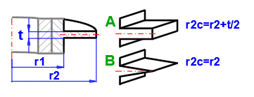
hfc ... Corrected fin height
Ap ...
Fin cross-sectional area
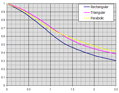
The x-coordinate of the graph is a
dimensionless value:
x = hfc^(3/2) * (hc / (Lambda * Ap))^(1/2)
hc ... Heat transfer coefficient [W/m²/K]
Lambda ... Fin material thermal conductivity [W/(m.K)]
The y-coordinate of the graph is the fin
efficiency ηf
ηf ... Fin efficiency
Efficiency of straight fins of rectangular, triangular, and parabolic profiles.
Efficiency of annular fins of constant thickness t.
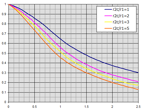
Individual curves relate to the radius ratio r2c/r1.
ηof = (1 - (n * Af) / At * (1 - ηf))
Where:
n ... Number of fins
Af
... Fin area
At ... Total area
ηf
... Fin efficiency
Radiant energy is transferred via electromagnetic radiation at various wavelengths. The topic of radiation heat transfer can be quite complex, so this document focuses only on fundamental problems commonly encountered in mechanical engineering practice.

Formulas presented use the notation shown in the accompanying figures.
hr = ɛ * δ0 * (Ts^4 - Tsky^4) / (Ts - Tsky)
Where:
ε ... Wall emissivity
[0...1]
δ0 ... Stefan-Boltzmann
constant, δ0=δ0 = 5.67e-8
[W/m²/K⁴]
Ts ... Wall temperature [°K]
Tsky
... Space temperature [°K]
Q1 = ε1 * δ0 * A1 * (T1K^4 - Tsky^4)
Where:
ε1 ... Wall emissivity
[0...1]
δ0 ... Stefan-Boltzmann
constant, δ0=δ0 = 5.67e-8
[W/m²/K⁴]
Tsky
... Space temperature [°K]
T1K ... Wall temperature [°K]
q1 = Q1 / A1
A1 ... Wall area [m²]
Q12 = (δ0 * A1 * (T1K^4 - T2K^4)) / (1/ε1 + A1/A2 * (1/ε2 - 1))
Where:
ε1 ... Emissivity
of wall 1 [0...1]
ε2 ... Emissivity
of wall 2 [0...1]
A1 ... Area of wall 1 [m²]
A2 ... Area of wall 2 [m²]
T1K ... Temperature of wall 1 [°K]
T2K ... Temperature of wall 2 [°K]
q12 = Q12 / A1
A1 ... Area of wall 1 [m²]
Q12 =(δ0 * (T1K^4 - T2K^4)) / ((1 - ε1) / (ε1 * A1) + (1 - ε3) / (ε3 * Ax) + (1 - ε4) / (ε4 * Ax) + (1 - ε2) / (ε2 * A2))
Where:
ε3 ... Emissivity
of shielding foil x [0...1]
ε4 ... Emissivity
of shielding foil x [0...1]
Ax ... Area of shielding foil x [m²]
q12 = Q12 / A1
A1 ... Area of wall 1 [m²]
Tx = ((R1 * T2K^4 + R2 * T1K^4) / (R1 + R2))^0.25
Where:
R1 ... Resistance between 1 and x
R2 ... Resistance between x and 2
R1 = (1 - ε1) / (ε1 * A1) + (1-ε3) / (ε3 * Ax)
R2 = (1 - ε4) / (ε4 * Ax) + (1 - ε2) / (ε2 * A2)
Q12 = (δ0 * (T1K^4 - T2K^4)) / Rsum
Rsum = R1 + R2 + R3
R1 = (1 - ε1) / (ε1 * A1) + (1 - ε3) / (ε3 * Ax)
R2 = (1 - ε4) / (ε4 * Ax) + (1 - ε5) / (ε5 * Ay)
R3 =(1 - ε6) / (ε6 * Ay) + (1 - ε2) / (ε2 * A2)
R1 ... Resistance between 1 and x
R2 ... Resistance between x and y
R3 ... Resistance between y and 2
q12 = Q12 / A1
A1 ... Area of wall 1 [m²]
Tx = (T1K^4 - Q12 * R1 / δ0)^0.25
Ty = (T2K^4 + Q12 * R3 / δ0)^0.25
Calculating the composite heat flux is not straightforward or directly solvable. The heat flux depends on a variety of parameters (temperatures, fluid properties, wall material, geometry, etc.) that change with the wall's temperature.
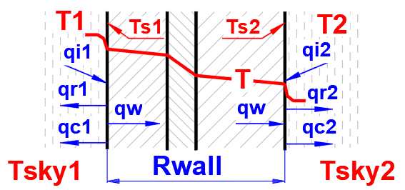
To determine the wall
temperatures Ts1 and Ts2, the heat flux equation is applied using the specified
fluid and wall parameters. The temperatures Ts1 and Ts2 are progressively
refined to satisfy the following equations:
Ts2 = Ts1 - q1 * Rwall; Q1 = -Q2
Q1 = (qi1 + qr1 + qc1) * A1
Q2 = (qi2 + qr2 + qc2) * A2
Q1 ... Total heat flux on the left
side [W]
Q2 ... Total heat flux on the right side [W]
The following
relationships (refer to previous sections) are used to calculate the heat flux
q:
qc = hc * (T - Ts) ... f (T, Ts, p, Rho, μ, Cp, λ.....)
qr = hr * (T - Ts) ... f (T, Ts, ε.....)
qi ... input parameter - direct irradiation (sun, external heat....)
Solving for wall temperatures Ts1 and Ts2 will, of course, change the values of hc1, hc2, hr1, and hr2. Therefore, a second iteration can be initiated manually, where new hc1 and hc2 values are used repeatedly to further refine the results.
Solution of the Ts1 and Ts2:
First estimate (n=1):
Ts1K[°K] = 100
*
(ABS((T1K
/
100)^4 - qi1
/ c0'))^0.25
Ts2K[°K] =
Ts1K - q1 * Rwall
qc1[W/m²] =
(T1K
-
Ts1K)
*
hc1
*
FinEff1
qc2[W/m²] = (Ts2K - T2K) * hc2
*
FinEff2
qr1[W/m²] =
(Tsky1
-
Ts1K)
*
hr1
qr2[W/m²] = (Ts2K - Tsky2) * hr2
q1[W/m²] = qi1 + qc1 + qr1
q2[W/m²] = qi2 + qc2 + qr2
ΔQ[W] =
Q1
-
Q2 = (q1 * A1 - q2 * A2) /
A2
ΔTs2 =IF(ABS(ΔQ)
> 1;(ΔQ/ABS(ΔQ)*(ABS(ΔQ)^0.5));ΔQ/2)
Aproximation (100 steps, half interval method, n = 2...100)
Ts1K(n) = Ts1K(n-1) + ΔTs2(n-1)
Ts2K(n) = Ts1K(n) - q1 * Rwall
qc1(n) = (T1K
-
Ts1K(n))
*
hc1
*
FinEff1
qc2(n) = (Ts2K(n) - T2K) * hc2
*
FinEff2
qr1 =
(Tsky1
-
Ts1K(n))
*
hr1
qr2 = (Ts2K(n) - Tsky2) *
hr2
qw(n) =
1
/
Rwall
*
(Ts2K(n)
- Ts1K(n))
q1(n) = qi1 + qc1(n) + qr1(n)
q2(n) = qi2 + qc2(n) + qr2(n)
ΔQ(n) =
Q1(n)
-
Q2(n) = (q1(n) * A1 - q2(n)
* A2) / A2
ΔTs2(n) = IF(ΔQ(n-1)*ΔQ(n) < 0; ΔTs2(n-1)/-2; ΔTs2(n-1))
Where:
c0′=δ0 * 1e8
= 5.67
δ0=5.67e-8 ...
Stefan-Boltzmann
constant
[W/m²/K⁴]
Rwall
... Wall thermal resistance
[m²K/W]
Tsky
... Ambient space temperature
[°K]
FinEff
... Fin efficiency [0 ... 1]
To accurately determine the longitudinal temperature change in a pipe with flowing fluid (liquid, gas), the following equation applies:
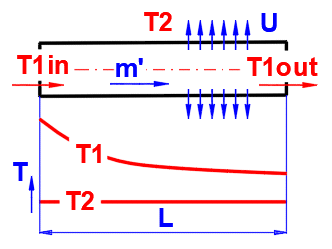
dTL = ABS(T1in - T2) * EXP(-Alpha * L)
T1in ... Inlet fluid
temperature [°C]
T2 ... Ambient temperature [°C]
L ... Distance from inlet [m]
Alpha = U / (m' * Cp)
U ... Linear heat transfer
coefficient [W/m/K]
m′ ... Mass flow rate of fluid [kg/s]
Cp ... Specific heat capacity of fluid [J/kg/K]
T1out =
T2 + dTL ...
(T1in>T2)
T1out = T2 - dTL .... (T1in<T2)
T1out ... Outlet temperature (temperature at distance L from inlet) [°C]
Power / Heat Load
Pw = -m' * Cp * (T1in - T1out) [W]
Cooling time calculations do not account for phase changes of the substance.

Phi = U * A * (1Ts - T2)
U ... Overall heat transfer
coefficient [W/m²/K]
A ... Internal surface area of pipe, tank [m²]
T1s ... Initial medium temperature inside [°C]
T2 ... Ambient temperature [°C]
Time = ((T1s - T2) * m * Cp * LN((T1s - T2) / (T1e - T2)) / Phi
m ... Mass of fluid [kg]
Cp ... Specific heat capacity of fluid [J/kg/K]
T1e ... Final medium temperature inside [°C]
Basic types of the heat exchangers
- Parallel flow heat exchanger
- Counterflow heat exchanger
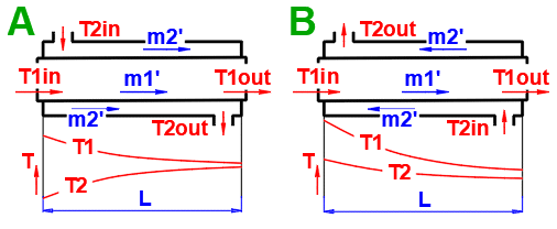
Derived Types of Heat Exchangers

Q1 = m1'
*
Cp1
*
dT1
Q2 = m2'
*
Cp2
*
dT2
Where:
m1', m2' ... Mass flow rate [kg/s]
Cp1,Cp2 ... Specific heat capacity [J/(kg·K)]
ΔT1,ΔT2 ... Temperature difference [°C]
Parallel flow heat exchanger.
Counterflow heat exchanger.
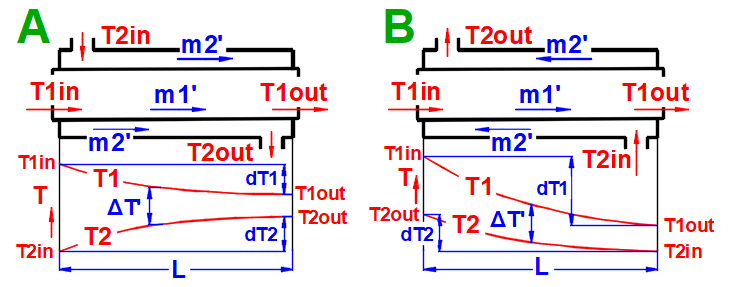
dT1 = T1Kout - T1Kin [°C]
dT2 = T2Kout - T2Kin [°C]
Parallel Flow A:
ΔTS' = ((T1Kin - T2Kin) - (T1Kout - T2Kout)) / (LN((T1Kin
- T2Kin) / (T1Kout - T2Kout)))
Counterflow
B: ΔTP' = ((T1Kin - T2Kout) - (T1Kout - T2Kin)) /
(LN((T1Kin - T2Kout) / (T1Kout - T2Kin)))
Type C-H Exchanger: ΔTX' = ΔTP' * Epsilon
T1Kin, T2Kin ... Inlet
fluid temperature [°K]
T1Kout, T2Kout ... Outlet fluid temperature [°K]
Epsilon ... Correction factor for the logarithmic mean temperature difference
[0.5 - 1.0]
The correction factor is approximated from tables using linear interpolation for C-H type exchangers.
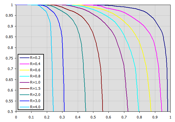
The heat capacity ratio R
R = (T1Kin - T1Kout) / (T2Kout - T2Kin)
Temperature Effectiveness P
P = (T2Kout - T2Kin) / (T1Kin - T2Kin)
Corresponding charts for Epsilon for various exchanger types are available in the cited literature.
Example chart (table approximation) for Type F exchanger: (Xaxis ... P, Yaxis ... Epsilon) For P=0.7, R=0.8 => Epsilon=0.85
A = ABS(Q1 / (Upl * ΔT'))
Where:
Q1,Q2 ... Heat flow [W], condition: Q1=−Q2
ΔT′
... Logarithmic Mean Temperature Difference (ΔTS′, ΔTP′, ΔTX′)
[°C]
Upl
... Overall heat transfer coefficient - flat plate [W/m²/K]
L = ABS(Q1 / (Ucyl * ΔT'))
Where:
Q1,Q2 ... Heat flow [W], condition: Q1=−Q2
ΔT′
... Logarithmic Mean Temperature Difference (ΔTS′,ΔTP′,ΔTX′)
[°C]
Ucyl
... Overall heat transfer coefficient - cylindrical wall [W/m/K]
Parallel Flow A: T1Out = T1in - Theta1S
Counterflow
B: T1Out = T1in - Theta1P
Type C-H Exchanger:
T1Out =
T1in - Theta1X
Parallel Flow A: T2Out = T2in + Theta2S
Counterflow
B: T2Out = T2in + Theta2P
Type C-H Exchanger:
T2Out =
T2in - Theta2X
Theta1S = (T1Kin - T2Kin) * FiS
Theta1P = (T1Kin - T2Kin) * FiP
Theta1X = (T1Kin - T2Kin) * FiX
Theta2S = C1 / C2 * Theta1S
Theta2P = C1 / C2 * Theta1P
Theta2X = C1 / C2 * Theta1X
C1 = m1'
*
Cp1
C2 = m2'
*
Cp2
Parallel Flow A: FiS = (1 - EXP(-U * OmegaS * LA)) / (1 + C1/C2)
Counterflow
B: FiP = (1 - EXP(-U * OmegaP * LA)) / (1 - C1/C2 * EXP(-U * OmegaP *
LA))
Type C-H Exchanger:
FiX =
(1 -
EXP(-U * OmegaX * LA)) / (1 - C1/C2 * EXP(-U * OmegaX * LA))
LA = Areq / (1 / Epsilon)
Where:
Areq
... Specified area for which outlet temperature is to be determined [m²]
Epsilon
... Correction factor for the logarithmic mean temperature difference (Type C-G
Exchanger) [0.5 - 1.0]
U ... Overall heat transfer coefficient - flat plate [W/m²/K]
Parallel Flow A: OmegaS = 1/C1 + 1/C2
Counterflow
B: OmegaP =1/C1 - 1/C2
Type C-H Exchanger: OmegaX =1/C1 - 1/C2
Rf = 1/Ud - 1/Uc
Ud = 1/ (Rf + 1/Uc)
Rf … Fouling factor [m²K/W]
Uc … Overall heat transfer coefficient for clean surface [W/m²/K]
Many engineering structures are exposed to solar radiation. This calculation determines the solar heat flux per unit area for specified conditions (surface orientation, date, hour, altitude, pollution) and the total daily energy input.
Used Relationships

Angles:
δ = 23.45 * SIN((360 * (284 + nn) / 365) * PI()/180)
nn ...
Sequential day of the year (1-365)
φ = ASIN((SIN(Latitude*PI()/180) * SIN(δ*PI()/180)) + (COS(Latitude*PI()/180) * COS(δ*PI()/180) * COS(15*PI()/180*(HH-12))))*180/PI()
Latitude ... Geographic Latitude [deg]
HH ...
Hour [0-24]
γs = ASIN(COS(δ*PI()/180) / COS(φ*PI()/180) * SIN(Tau*PI()/180))*180/PI()
Tau = 15 * (HH-12) ... Solar hour angle [deg] (morning (-), afternoon (+))
θ = ACOS((SIN(φ*PI()/180) * COS(β*PI()/180) + COS(φ*PI()/180) * SIN(β*PI()/180) * COS((γs - γ)*PI()/180)))*180/PI()
β ... Surface tilt angle (0-90) [deg]
γ ... Surface azimuth angle (+-180) [deg]
Radiation Power:
Qon = SolarConst * (1 + 0.033 * COS((360*nn/365)*PI()/180))
The solar radiant flux outside the
atmosphere varies by ±3.3% throughout the year (due to Earth-Sun distance).
SolarConst
... Solar Constant (mean value 1367 W/m²)
Qbn = Qon * EXP( -(Zcoeff / EpsilonCoeff))
Zcoeff ... Atmospheric pollution coefficient (1.5 -6)
EpsilonCoeff = (9.38076 * (SIN(φ*PI()/180) + (0.003 + SIN(φ*PI()/180)^2)^0.5)) /
(2.0015 * (1-Lv*10^-4))+0.91018
Lv ...
Altitude [m]
QbT = Qbn * COS(θ*PI()/180)
Qd = 0.33 * (Qon - Qbn) * SIN(φ*PI()/180)
QdT = ((1+COS(β*PI()/180))/2) * Qd
QrT = Rhog * ((1 - COS(β*PI()/180))/2) * (Qb + Qd)
Qb = QbT * SIN(φ*PI()/180) / COS(θ*PI()/180)
Rhog ...
Ratio of reflected to incident solar radiant flux density
(0-1).
QT' = QbT + QdT + QrT
QT = As * QT'
As ... Total irradiated area
Q = QT * Efficiency / 100
Efficiency ... Conversion efficiency of solar radiation to usable energy (0-100).
To calculate Pw, the value of Q is determined every 30 minutes from t=0-24h. These values are then summed to obtain the total Pw
Pw = Sum (Q(t) * 0.5) [t=0-24]
The calculations provided here cover frequently encountered problems in the field of thermomechanics. As these problems are only loosely related, there's no universal procedure outlined. Procedures vary based on the specific problem. If your task falls within the scope of the problems addressed, we recommend reviewing the examples provided in the help documentation. For each calculation type, several typical examples are usually included to familiarize you with the specific procedure.
In this paragraph you set the calculation units.
Select the desired system of calculation units in the list box. After switching over the units, all values will be changed immediately.
Type the value you want to convert into the input box on the left. Select source units and target units on the right.
This section covers basic energy calculations, including heating, cooling, phase change, and combustion. Unless otherwise specified, the coefficients in the tables are provided for a temperature of 20 C and a pressure of 0.1 MPa.
Energy must be added or removed to heat or cool a substance.
Select the material group. The pointer in the material table (next line) will be set to the first material of the corresponding type.
Select the material.
These are informational values and do not affect the calculation.
The value of Cp for the selected material is shown in the green field. You can input your own value by unchecking the button.
Enter the mass of the material being heated or cooled. The switch on the right determines which value should be calculated.
Enter the temperature change.
The energy expended for the temperature change.
Energy must be added or removed during a phase change (solid → liquid → gas).
Select the material. The melting temperature [TM] and boiling temperature [TB] are indicated in square brackets.
The values for CpM and CpB of the material selected from the list are in the green field. You can input your own values by unchecking the button.
Enter the mass of the medium. If the checkbox is selected, the value from the previous calculation will be used.
The energy expended or gained during the phase change.
Heat of Combustion
(Higher Heating Value - HHV) is the amount of heat released during the isobaric combustion of 1 mole of a compound in gaseous oxygen to final oxidation products. It's assumed that the water released by combustion condenses, and the chemical reaction energy doesn't need to be reduced by its latent heat.
Heating Value
(Lower Heating Value - LHV) assumes water is in a gaseous state at the end of the reaction.
Therefore, the HHV value is always greater than or equal to the LHV value. Equality occurs when no water is formed during combustion.
Select the combusted material from the list.
For the Lower Heating Value (LHV), water is assumed to be in a gaseous state at the end of the reaction.
The Heat of Combustion (HHV) value is accurate for the combustion of defined compounds (H2, CH4O, etc.). For fuels containing various mixtures (coal, petroleum products, natural gas, etc.), typical values may be lower or higher than the tabulated value. The estimated deviation from tabulated values is indicated in the green field. You can input your own HHV value by unchecking the button.
Enter the mass of the combusted material.
Combustion efficiency indicates how much energy from the fuel is transferred to the heat transfer medium.
Gas boilers:
Condensing boilers: up to 98%
Low-temperature boilers: up to 89%
Conventional boilers: up to 84%
Solid fuel boilers:
Wood or wood pellet gasification boilers: up to 92%
Automatic coal boilers: 80% to 90%
Coal and other solid fuel boilers: over 70%
The energy gained from fuel combustion.
This section covers the periodic table of elements, calculation of molar mass and Poisson's constant for elements, compounds, and their mixtures. The second part calculates the state and state change of an ideal gas (pV=mrT).
Enter the chemical formula of the compound. After pressing the ">>" button, the formula is broken down into individual elements and the corresponding list is populated below. If you want to calculate a mixture of compounds, separate them with a "+" sign. When reading the formula, the sequential number of the compound (element) in the mixture is added in the last column of the table.
Compound Examples: h2so4, H2O, cO2, C4H10O, C2H3ClO2
Mixture Examples:
Air: N2+O2+Ar+CO2
Alcohol(40%)+Water(60%): C2H5OH+H2O
The buttons "1-20", "21-40"... populate the table with the corresponding elements.
The parameters of the selected element from the list are displayed on the respective row.
The "Clear" button clears rows 2-20.
Element symbol.
Number of atoms.
Atomic mass.
Molar mass.
Element density.
Specific heat capacity.
Specific heat of fusion (heat of fusion).
Specific heat of vaporization (heat of vaporization).
Thermal conductivity.
Melting point.
Boiling point.
Compound sequence number.
To calculate mixture parameters, it's necessary to determine the compound sequence number. Individual elements within a compound must have the same sequence number.
In the previous table, you can define individual elements and compounds marked by a sequence number. In this table, after entering the mass fraction in the mixture, you can determine the total molar mass of the mixture.
For ideal gases, Poisson's constant is determined by the number of degrees of freedom of the given molecule.
Molar mass of an individual element or compound.
Enter the mass fraction of each component in the mixture. If the checkbox to the right is selected, the original values are retained when populating the mixture from the formula [3.2].
If the checkbox is deselected, each mixture component is set to the same value.
A red sum cell at the end of the row indicates that the sum is not 100%.
Molar mass of the mixture.
r = R / Msum
R ... Universal gas constant (8314.46261815324 J/kmol/K)
Msum ... Molar mass of the gas
The ratio of specific heats of a gas at constant pressure and constant volume κ=cp /cv.
For ideal gases, Poisson's constant can be determined from the number of degrees of freedom of the molecule.
Click the "▼M,κ▼" button to transfer M and κ values to the gas definition below.
This calculation allows for solving the state of an ideal gas (pV=mrT), its state change, and determining corresponding energy values (entropy, enthalpy, heat, work...). After selecting (or defining physical parameters for) the working gas, you can determine its operating parameters (mass m, pressure p, volume V, and temperature T) based on the ideal gas equation of state: p⋅V=m⋅r⋅T
r=R/M
M=m/N
Where:
p ... Absolute pressure [Pa]
V ... Volume [m^3]
m ... Mass [kg]
T ... Temperature [K]
R ... Universal gas constant R=8314.46261815324 [J/kmol/K]
M ... Molar mass of gas [kg/kmol] (air 28.966 kg/kmol)
N ... Amount of substance [kmol]
r ... Specific gas constant [J/kg/K] (air 287.0427 J/kg/K)
A ... Example of a simple thermodynamic system, ideal gas p⋅V=m⋅r⋅T.
B ... Reversible processes can be described more generally as polytropic processes, where the heat capacity of the (closed) system is constant. In a polytropic process, all state variables (p, V, T) generally change. For a polytropic process in an ideal gas, the equation p⋅Vn=const. holds. The curves of changes for different n values are marked in the p-V and T-s diagrams.
C ... Carnot cycle. An example of an ideal heat engine consisting of two isothermal and two adiabatic processes.
D ... Curves of fundamental reversible state changes:
n=0 ,p=const, Isobaric, (dp=0, wt=0, q=Δh, w=Δh-Δu)
n=1 ,T=const, Isotermic, (dT=0, Δu=Δh=0, q=w=wt)
n=κ ,s=const, Isoentropic, (ds=0, q=0, w=-Δu, wt=-Δh)
n=∞ ,v=const, Isochoric, (dv=0, w=0, q=Δu, wt=Δu-Δh)
Select the working gas from the list. If it's not in the list, uncheck the button on the right and enter the M, cp, and κ values.
The specific heats cp, cv, and κ of the gas change with temperature. For predefined gases, you can define a reference (working) temperature. The green field shows the recommended value (average of max/min values of T1...T6). Click the "◄" button to transfer the recommended value to the input cell.
If defining gas parameters, enter the value.
r = R / M
r .... Specific gas constant (air 287.0427 J/kg/K)
R ... Universal gas constant (8314.46261815324 J/kmol/K)
M ... Molar mass of gas (air 28.996 kg/kmol)
If defining gas parameters, enter the value.
The ratio of specific heats of a gas at constant pressure and constant volume κ=cp /cv.
For ideal gases, Poisson's constant can be determined from the number of degrees of freedom of the molecule.
Enter the amount of substance. The corresponding mass is displayed on the next line. Pressing the "◄ N1" button populates the amount of substance corresponding to mass m1 (point 1).
Pressing the "m1▼" button moves the mass value to the m1 field (point 1).
Equilibrium state and state change of an ideal gas (Equation of State). There are 6 points (i=1−6) available. At each point, the equilibrium state of the gas can be determined by its state variables p(i), V(i), T(i). For points 2-6, it is possible to determine how the state changed from state (i−1) to (i). State changes can be observed in the "p-V" and "T-s" graphs.
Determining the equilibrium state:
Enter the values you know sequentially into the white cells of the selected point. In the green cells on the right, values are continuously calculated that must be used to achieve the equilibrium state (p⋅V=m⋅r⋅T). Transfer the suggested value to the white cell using the "◄" button. The text "▼ =OK ▼" signals that the equation is satisfied. If the equation of state is not satisfied, the text "▼ Error ▼" is displayed.
State changes:
If you set the gas parameters at point 2 (3, 4...), you can determine the changes for energy values (entropy, enthalpy, heat, work...) relative to the previous point.
Recommended procedure 1:
Isobaric (p=const), isochoric (V=const), isothermal (T=const) changes.
• Use the "►" button to transfer the state (m,p,V,T) to the next point. (The "►=" button inserts a link to the previous point. For example, p2 will be "=p1", V2 will be "=V1", etc. The cell color will be gray).
• Change one input value. Suggested values for achieving equilibrium are immediately displayed in the green column.
• Use the "◄" button to transfer the selected suggestion to the input (white) cell.
Recommended procedure 2:
Polytropic process - the heat capacity of the (closed) system is constant. In a polytropic process, all state variables (p, V, T) generally change. For a polytropic process in an ideal gas, the equation p⋅Vn=const. holds.
• Use the "►" button to transfer the state (m,p,V,T) to the next point.
• Change only one input value (p or V or T).
• Enter the polytropic exponent n and press the "◄ Polytr.◄" button. The input cells are populated with values to achieve the desired n.
Gas mixing - "3 = Mix (1+2)" button
Calculation of gas parameters resulting from mixing two parts (1+2) with different parameters p, V, T.
m = m1 + m2
p = m / M * R * T / V
V = V1 + V2
T = (m1 * T1 + m2 * T2) / (m1 + m2)
Reversible processes can be described more generally as polytropic processes, where the heat capacity of the (closed) system is constant. In a polytropic process, all state variables (p, V, T) generally change. For a polytropic process in an ideal gas, the equation p * Vn=const. holds.
Enter the desired value of n for the transition between two states (previous and current) into the input cell. To the right of the input cell, the current value calculated from p, V, T is displayed. The dropdown list contains significant and frequently used values.
• Use the "►" button to transfer the state (m,p,V,T) from the previous point.
• Change only one input value (p or V or T).
• After pressing the "▲Polytr.▲" button, the input cells are populated with values to achieve the desired n.
If n="?", the values (m,p,V,T) are identical to the previous point.
For selected values of n:
n=0, p=const, Isobaric, (dp=0,wt=0,q=Δh,w=Δh−Δu)
n=1, T=const, Isothermal, (dT=0,Δu=Δh=0,q=w=wt)
n=κ, s=const, Isentropic, (ds=0,q=0,w=−Δu,wt=−Δh)
n=∞, v=const, Isochoric, (dv=0,w=0,q=Δu,wt=Δu−Δh)
n=ln(p2/p1)/(ln(p2/p1)−ln(T2/T1))
n=(ln(V2/V1)−ln(T2/T1))/ln(V2/V1)
Typical polytropic exponent values:
Piston compressor: n=1.2–1.3 Process with partial heat rejection, typical value for slow compressors with cooling.
Axial compressor: n=1.35–1.4 High-speed turbocompressors with minimal heat rejection, closer to an adiabatic process (γ≈1.4 for air).
4-stroke gasoline engine (compression): n=1.3–1.35 Compression of fuel mixture with partial heat rejection to cylinder walls.
4-stroke diesel engine (compression): n=1.35–1.4 Higher compression ratio and compression of pure air, less heat loss than a gasoline engine.
This row displays the polytropic specific heat capacity and the gas state:
• "▼ =OK ▼". Equilibrium state achieved.
• "▼ Error ▼". If equilibrium state is not achieved.
If cn="?", the values (m,p,V,T) are identical to the previous point.
The "►►" button copies the values (m1,p1,V1,T1) to all other points.
Enter the mass of the working fluid. If the input digit is red, it's just a warning that the mass value in the previous point is different. This may not be an error!
Enter the absolute pressure of the working fluid.
Enter the volume of the working fluid.
Enter the temperature of the working fluid.
Values for individual points (states) in a single table.
Entropy
S1 = (cv * LN(T1) + r * LN(V1)) * m1
S2 = (cv * LN(T2) + r * LN(V2)) * m2
The table shows changes when transitioning from state 1 to 2 (or 2-3, 3-4...). The state change is displayed in the p-V and T-S state diagrams. You can toggle the display in the table and graph using the respective buttons. The column labeled "Sum" contains the sum of changes.
If n="?", the values (m,p,V,T) are identical at the respective points 1-2, 2-3,....
For selected values of n:
• n=0, p=const, Isobaric, (dp=0,wt=0,q=Δh,w=Δh−Δu)
• n=1, T=const, Isothermal, (dT=0,Δu=Δh=0,q=w=wt)
• n=κ, s=const, Isentropic, (ds=0,q=0,w=−Δu,wt=−Δh)
• n=∞, v=const, Isochoric, (dv=0,w=0,q=Δu,wt=Δu−Δh)
Entropy change
ΔS = S2 - S1 = (cp * Ln(T2/T1) - r * Ln(p2 / p1))*m1
ΔS = S2 - S1 = (cv * Ln(T2/T1) + r * Ln(v2 / v1))*m1
Change in internal energy
ΔU = cv*(T2 - T1) * m1
Change in enthalpy
ΔH = cp * (T2 - T1) * m1
Polytropic heat.
Energy transfer to the system in the form of heat (Q>0 when the system receives heat).
Q = m * cn * (T2 - T1)
Q = -((n - kappa) / (kappa - 1)) * W
Polytropic boundary work.
Energy transfer through various forms of work (W>0 when the system performs work).
W=Q-dU=m * (cn - cv) * (T2 - T1) = m * (r / (n - 1)) * (T1 - T2)
W=m * r * T1 / (n - 1) * (1 - (V1 / V2)^(n-1))
Polytropic pressure work (technical)
Wt=n * W
W ... Polytropic boundary work [J]
n .... Polytropic exponent [~]
Two commonly used state graphs are displayed:
Pressure (p) - Volume (V)
Temperature (T) - Entropy (S) Each point is labeled with a number.
Individual segments can be toggled on/off using the buttons on the left.
Comprehensive solution for heat transfer through a composite wall (max. 10 layers).
The calculation includes:
- Convective heat transfer (definition of fluids, flow type, definition of objects)
- Conductive heat transfer (definition of the wall, thickness, and material parameters of individual layers)
- Radiant heat transfer (heat radiation, wall irradiation)
- Tube bundle solution (heat exchangers)
- Finned surface solution
The calculation provides heat transfer parameters like the overall heat transfer coefficient "U" from medium (T1) to medium (T2), thermal resistance "R", heat flux values, and many others.
The calculation is flexible and also allows for partial calculations, such as:
- Determining the heat transfer coefficient only between the wall and the medium
- Determining the heat transfer coefficient of the wall itself
- Solutions for walls in a vacuum and walls in direct contact with a heating or cooling surface
A complete definition of a "wall" can be saved to create a database of solutions that can be used in other calculation sections.
For example: cooling/heating of pipelines and tanks, heat exchanger calculations, and solving problems that involve several different walls.
Procedure for a complete heat transfer calculation from medium 1 to medium 2:
- Define the boundary conditions of the medium
- Define the shape and individual layers of the wall
- Select the shape and flow type for the surface of the wall for medium 1 and 2.
- Define the heat transfer parameters for radiation for the inner and outer surfaces of the wall
The result of the calculation is the overall heat transfer coefficient "U", thermal resistance "R", and heat flux values.
Enter the temperature of the medium inside and outside.
For flat walls, the temperature on the left and right according to the image.
Enter the pressure for medium 1 and 2.
In this section, select the wall shape and define the parameters of the individual layers.
Select the wall type.
Select the material group. The pointer in the material table (next row) will be set to the first material of the corresponding type.
Temperature curves in the wall (cylindrical and spherical surface) are replaced by a straight line.
x ... wall thickness
y ... temperature profile
Select the layer material. By pressing the "Add/Replace" button, the selected material is either added to the row where the active cell is located or to the first row without a description in the definition table below. If the row already contains values for b, ρ, λ, Cp, they will be overwritten. The "Clear All" button removes rows 2-10.
The list shows the individual layers of the wall.
A layer is included in the wall calculation if it has a non-zero thickness.
If the table is inconsistent (e.g., an unfilled row), a "Check" message is displayed. Please check the input.
If the wall type is cylindrical or spherical, the inner diameter of the composite wall must be entered. The inner diameters of the subsequent layers are calculated from the entered layer thickness.
The thickness of the wall layer.
The density of the material.
This value does not affect the heat transfer calculation. It is used to determine the total weight of the wall.
Thermal conductivity
Unit conversion
1 [W/m/K] = 0.57782 [BTU/h/ft/F]
1 [BTU/h/ft/F] = 1.7306 [W/m/K]
Specific heat capacity
Unit conversion
1 [J/kg/°K] = 0.0002388459 [BTU/lb/°F]
1 [BTU/lb/°F] = 4186.8 [J/kg/°K]
Thermal resistance of the wall per unit of internal area
Unit conversion
1 [m²K/W] = 5.6744659 [h.ft²F/Btu]
1 [h.ft²F/Btu] = 0.17622804 [m²K/W]
The temperature in the first row is the inner (left) wall temperature t(1).
The other rows show the temperatures at the interfaces of the wall layers.
The weight of the wall layer per unit of internal area.
When selecting a cylindrical/spherical surface, the value is recalculated.
This section deals with convective heat transfer (a medium flowing over a surface). The image shows the options. For a solution, it is necessary to define the medium parameters, the flow type, and the parameters of the surface being flowed over.
A) Forced convection inside a profile (01-06)
B) Forced convection around a profile (07-13)
C) Free convection - flow caused by different densities of a heated/cooled medium (14-19)
It is also possible to solve for flow over a tube bundle and flow over a finned profile.
The calculation can be used in two ways.
A) Comprehensive heat transfer from medium 1 to medium 2
In this case, the calculation chain (T1=>Ts1=>Ts2=>T2) must be maintained. The checkboxes at [4.14] must be checked.
B) Solving heat transfer between the wall and the medium
It is possible to directly enter the wall temperature by unchecking [4.14]. In this case, only convective heat transfer for the given wall is solved. The valid result is then only the value of the heat transfer coefficient hc, or hc+hr for the selected side of the wall.
The list contains the most commonly solved problems. Selecting from the list sets the corresponding flow type for 1 and 2 and enables the switches for using the proposed values (green field).
Define the parameters for the medium inside and outside (left and right).
The following options are available:
A - Vacuum. If there is a vacuum on the wall side, convective heat transfer is zero.
B - Direct contact. A heat/cooling source is directly connected to the wall side, and heat transfer occurs with negligible losses. For example, the bottom of a pot on a stove.
C - Numbered, predefined, commonly used liquid and gaseous substances. For these substances, the required parameters are defined as a function of temperature (pressure).
If the liquid / gas is not in the list, uncheck the button on the density value row and manually enter all the parameters for the liquid / gas for the definition temperature Tdef.
The value in the green field is the result of the complete heat transfer calculation from medium 1 to medium 2 (radiation, convection => conduction => convection, radiation). This value is obtained by iteratively adjusting the wall temperature so that the heat flux Q1 and Q2 are identical.
By unchecking the button, you can enter your own value.
In that case, the result of the calculation is the heat transfer from radiation+convection on the respective side of the wall.
The critical equations for calculating the heat transfer coefficient hc from various authors use different temperatures to define the parameters of the liquid / gas.
a) average film temperature at the wall Tdef = (T + Ts) / 2
b) mean temperature Tdef =T
For most equations, Tdef = (T + Ts) / 2 is used.
If direct value entry is not selected (first option), automatic switching is performed when selecting the critical equation [4.23].
Dynamic viscosity for wall temperature Ts
Dynamic viscosity for definition temperature Tdef
Select the flow type. In the list, the first letter means:
A-Forced convection
B-Free convection
The number corresponds to the image above, and the lowercase letter after the number specifies the equation (source) that is used.
Select the flow type for medium 1 and medium 2, corresponding to your problem according to the image above. The combination of selections should make sense. For example, it is not possible for medium 1 to flow in a circular tube and medium 2 to flow over a sphere.
An unsuitable combination will be indicated by a red "Check" message between the selection lists.
**) Annular flow 05
If this option (05) is selected as the inner (left) wall, heat transfer is solved for the outer diameter d1 (between the flowing fluid and the outside).
If this option (05) is selected as the outer (right) wall, heat transfer is solved for the inner diameter d2 (between the flowing fluid and the inside).
The permitted combination is thus:
1) A-05 ... A-07 and/or
2) A-01 ... A-05 (suitable if you want to use longitudinal fins for the outer surface of the pipe)
If flow type A-Forced convection is selected, enter the flow velocity.
After selecting the flow type, the variable names according to the image and the units are set accordingly.
The green fields contain proposed values.
Finning is an effective solution to increase the heat transfer area and thus increase heat transfer.
If the flowed-over surface has fins, set the switch to "Yes."
The fin shape itself is defined in section 4a. You can switch to it using the ">>Definition [4a]" button.
Based on the fin dimensions (section 4a), a new heat transfer area At1, At2 is determined. This is used for the proposed value A1 and A2 [4.37].
Although finning increases the heat transfer area, it also reduces the heat transfer efficiency ηf1, ηf2. The heat transfer coefficient hc1, hc2 is corrected by this efficiency.
Tube banks are often used to increase the heat transfer area. If you want to solve this problem, select the tube arrangement A or B from the list (see image). On the following lines, fill in the parameters for the tube spacing. For this problem, medium 1 must flow inside the tube (01-06) and medium 2 must flow around the tube (07-11).
If an incorrect combination of flow types is selected, a "Check" message is displayed.
Enter the distance between the tubes in the vertical direction ST and in the horizontal direction SL according to the image.
The default is twice the outer diameter of the tube.
Enter the number of rows in the vertical direction m and the number of columns in the horizontal direction n according to the image.
Depending on the arrangement and number of rows and columns, the number of tubes in the bundle is determined (green cell).
If the number of tubes in your problem differs, you can enter your own value. This will affect the proposed heat transfer area.
On row [4.24], you enter the velocity v2, which is the flow velocity before entering the tube bundle. Inserting the tubes reduces the flow cross-section. This increases the flow velocity around the tubes (v2max) for medium 2.
The green field contains the proposed value, which is based on the entered dimensions and velocity v2. If your design is atypical, uncheck the button and enter your own value.
The green field contains the proposed value based on the previously defined parameters.
For medium 1, it is the left side (for a plate) or the inner circumference x tube length. For medium 2, it is the right side (for a plate) or the outer circumference x tube length.
If finning or flow through a tube bundle (heat exchangers) is selected, the heat transfer area is changed accordingly.
1) Tube bundle ... A * number of tubes
2) Finning ... At (from the Finning section)
3) Finned tube bundle ... case 1 * case 2
The case of simple flow-over (without finning) is checked, where the heat transfer area for medium 1 should be less than or equal to the area for medium 2. If this is not the case, you are alerted by the "Check" message.
When using critical equations to calculate the heat transfer coefficient hc, dimensionless parameters (similarity numbers) are used, which allow for solving similar shapes of different dimensions and different surrounding conditions. A more detailed explanation is in the help section or in specialized literature.
The most important similarity numbers are listed here.
With the button, you move the proposed (calculated) hc1, hc2 value from the green cell to the input cell. The iteration will run 5 times.
The most important similarity number is the Nusselt number. The following relationships then apply for calculating the heat transfer coefficient hc:
Nu = hc * Dh / λ ===>
hc = Nu * λ / Dh
λ ... Thermal conductivity of wall material
Dh ... Characteristic dimension (D, Dh, a ..... based on the shape)
The green field shows the calculated heat transfer coefficient hc1 and hc2. The calculation is based on the parameters of the flowing medium, temperatures, and flow type. If you want to use it, press the "Iterate hc1<<, hc2<<" button.
Changing hc1 and hc2 will naturally lead to a change in temperatures, and thus a change in the parameters of the flowing medium and a new hc calculation. Therefore, the replacement is performed 5 times in a row.
The smaller "hc1" and "hc2" buttons then replace only one coefficient.
Two values are given for each medium
- heat flux per unit area (A1, A2)
- total heat flux through area A1, A2
This section of the calculation deals with simple cases of radiation / irradiation.
- radiation into space (e.g., a large hall)
- radiation into space (normal atmospheric environment)
- surface irradiation (e.g., solar radiation)
For most common situations, these cases are sufficient. If you need to solve more complex radiant heat transfer problems, use section [7.0] and use the calculation result as a positive / negative radiant flux incident on the given surface.
The image indicates the energy flow (+) and (-) with respect to the wall surface 1 and 2.
Select the material group. The pointer in the material table (next row) will be set to the first material of the corresponding type.
The "Search" button will attempt to find the corresponding material for the first and last layers of the wall in the material table.
Select the surface material. A typical emissivity for the selected material is given in parentheses after the name. If a range of values is given, their average is offered as a proposed value (green).
By unchecking the button, you can enter your own value for the wall surface emissivity.
Determine if heat is being radiated into space.
Select the appropriate option (see image)
A ... No heat transfer by radiation. This is an enclosed surface (e.g., the inner wall of a pipe).
B ... General radiation into space (interior and exterior). For the radiant heat transfer calculation, the medium temperature T1 or T2 is used relative to the wall temperature Ts1 or Ts2.
If you do not know the exact conditions, choose this option.
C, D, E ... To determine the radiation between the wall and the sky, the equivalent sky temperature for a black body, Tsky [°K], is determined. This temperature takes into account the non-uniformity of atmospheric temperature and radiation at certain wavelengths.
Calculation of heat flux qr' = ε * σ * (Tsky^4 - Ts^4)
For the relationship between sky temperature and local air temperature, approximate relationships are used:
C ... Tsky = Ta - 6°C
D ... Tsky = Ta - 12°C
E ... Tsky = 0.0552 * Ta^1.5 (platnost -30...+50°C)
where: Ta ... ambient air temperature [°K] (for example: Ta = T2[°C] + 273.15)
The green field contains the proposed value for the radiating area. If finning or a tube bundle is not used, the area Ar1, Ar2 is the same as the heat transfer area A1, respectively A2. [4.37]
If finning or flow through a tube bundle is selected, the radiating area is changed accordingly.
1) Tube bundle ... A * number of outer tubes / 2
2) Finning ... A + area of outer fins
3) Finned tube bundle ... case 1 * case 2
Two values are given for each medium.
- heat flux per unit area (A1, A2)
- total heat flux through area A1, A2
If you need to solve for radiant heat transfer other than radiation into space. For example: solar radiation, data from section [7.0], your own calculation ....
Enter the intensity of the radiation incident on the surface. Use the switch on the right to set:
- *1: The calculation uses the entered value directly and does not consider the wall emissivity ε. It is assumed that the emissivity is already included in the radiation magnitude. For example, the result of a calculation from section [7.0].
- *ε: The calculation multiplies the entered value by the selected wall emissivity coefficient ε. It is assumed that the radiation level is known. For example, solar radiation.
Solar radiation
Its maximum value on the Earth's surface is around 1100 [W/m²] (350 [Btu/h/ft²]. For accurate values, use section [8.0].
Enter / Select the size of the irradiated area.
By selecting the first item from the list, you can enter the size of the irradiated area Ai directly.
Other items 1-5 (see image) allow the calculation of the irradiated area Ai from the heat transfer area A1, A2 depending on its shape.
Two values are given for each side of the wall
- average heat flux per unit area A1, A2 (since only a part of the heat transfer area may be irradiated, the input value "ir" is multiplied by the ratio Ai/A).
- total heat flux through the area
The sum of all components.
The heat transfer coefficient for the respective side of the wall. It includes convection, radiation, and irradiation.
The heat flux for the respective side of the wall. It includes convection, radiation, and irradiation.
The calculation does not solve for a potential change in the temperature of the flowing medium.
qcri' = qc' + qr' + qi' … specific per unit of inner / outer area
Qcri = Qc + Qr + Qi … total
Two values are given for each medium
- heat flux per unit area
- total heat flux through area A1, A2
For various other calculations, it is necessary to know the overall heat transfer coefficient through the wall U or the thermal resistance of the wall R=1/U. The following are used in the calculations:
1) Values based on the inner (1) or outer (2) area. They are also valid for cylinders and spheres.
2) Values based on the unit length of a defined cylinder [4.5, 4.8].
3) Values based on a defined sphere [4.5, 4.8].
In literature and catalogs, the parameter "Thermal resistance of the wall" is often given. This refers only to the thermal resistance of the composite wall defined in the table above.
For quick orientation, a calculation for the heating / cooling of the working medium is also provided, if the problem being solved corresponds to it (complete calculation, long pipe, long flowed-over surfaces, etc.).
The switch between the headings lets you choose whether the media are flowing co-currently or counter-currently.
Below, enter the parameters for the flowing medium for the inner (left) side and for the outer (right) side of the wall for temperatures T1 and T2.
When calculating the proposed flow area (green cell), the following cases can occur:
1) The fluid flows through a precisely defined cross-section (01-06). The value in the green field is exact. E.g., a circular tube with a cross-section of Af = PI * (D / 2)
2) The fluid flows over a pipe (07-11). A value equal to the perpendicular cross-section of the pipe (outer dimension) is proposed. E.g., a circular tube with a cross-section of Af = D * L
3) The fluid flows through a tube bundle. Af = m * ST * L
4) Free convection (13-19). The flow area is equal to the flowed-over area.
By unchecking the button, you can enter your own value.
From the entered flow velocity v1 (v2) [4.24], the flow area Af, and the density Rho, the flow rate is calculated.
In the list on the right, you can select the units that are displayed.
From the entered heat transfer area A [4.37], the flow area Af, the density Rho, the specific heat capacity Cp', the flow rate m', and the calculated heat transfer coefficient U, the outlet temperature Tout1 and Tout2 are calculated.
The heat flux is calculated from the difference in medium temperatures at the inlet and outlet and from the properties of the working medium.
The heat flux thus differs from the Qcri [4.62] data, where no change in medium temperature is considered.
Two values are given for each medium
- average heat flux per unit area
- total heat flux through area A1, A2
Solving wall heat transfer requires entering and selecting dozens of parameters. Therefore, it is possible to name and comment on the solution and save it to a list for future use, or to load the parameters in other sections of this calculation.
Save the current state of all parameters - the solution - with the "Save solution" button.
Solutions are saved on the "Walls" sheet. One row contains one saved solution.
When the "Save solution" button is pressed, the list is searched, and if a record with the same name exists, it is overwritten with the current state. If the name does not exist in the solution list, the last filled row on the "Walls" sheet is found, and the current solution is written to the next row.
The "Walls" sheet is freely accessible and can be edited normally with Excel tools (e.g., deleting unnecessary solutions - rows).
Retrieving a single value from a saved solution.
If you need to retrieve a specific value and use it in your own formula, the GetWallProp function is available to do so.
Syntax:
GetWallProp(ID;value_name)
ID ... The row number on the "Walls" sheet that contains the saved solution
value_name ... The name of the value you want to retrieve.
Enter the name of the wall heat transfer solution.
The solution will be saved under this name in the list of saved solutions.
Automatically generated text that is added to the description and contains basic information, including:
T1(), T2() ... Temperatures, (medium)
|mm| ... Wall thickness
U1 ... Heat transfer coefficient
q1, q2 ... Total specific heat flux
Enter a description. This will allow for better orientation when subsequently viewing already saved solutions.
After selecting a solution from the dropdown list below, press the "Load solution" button.
Use the buttons on the right to navigate through the list of saved solutions.
The solution save date is in the format "yyyymmdd - hh:mm:ss".
The dropdown list contains wall heat transfer solutions that are saved on the "Walls" sheet.
Basic info about the selected wall heat transfer solution.
Description of the selected wall heat transfer solution.
This section is directly connected to the previous one and deals with the finning of the flowed-over surface. It is used to increase the heat transfer area and thus increase heat transfer. For use, finning must be enabled in the previous section [4.29].
Based on the selected flow type in the previous section [4.23], the corresponding fin type 1-4 is assigned according to the figure.
From the previous section [4.0], the values λ, hc, T and Ts are used for the fin calculation.
The value for the thermal conductivity of the material λ is taken from the first and last layer of the composite wall.
Depending on the selected flow type [4.23] and the entered dimensions, the finned field width "a" is calculated for the following fin types:
1) a = surface length
2) a = pipe length
3) a = pipe internal circumference
4) a = pipe external circumference
You can enter your own value for the field width after unchecking the box.
Select the fin shape according to the figure.
Based on the dimensions of the finned surface and the flow type, the fin dimensions are preset (green cells). You can enter your own dimensions after unchecking the box.
The maximum number of fins that can be used based on the field width and fin dimensions is proposed in the green cell. You can enter your own value after unchecking the box. For example, if only a part of the surface / pipe is finned.
- Af ... Area of a single fin (fin only).
- At ... Complete heat transfer area (fin area x number of fins + remaining area of the base profile).
The value of the complete finned heat transfer area At is used as a recommended value on line [4.37].
Parameter x is used to find the fin efficiency in the corresponding graphs (it performs the calculation).
The overall efficiency includes the ratio of the fin area to the total finned area and is used when calculating the heat flux qc', Qc [4.43].
This section addresses the temperature change of a flowing substance in piping and the cooling time for a given temperature drop in pipes, vessels, and tanks.
Select the fluid flowing in the piping.
If the fluid is not in the list, enter the Cp value on line [5.3].
Enter the defining temperature. The Cp value for the selected fluid will be calculated from this temperature on line [5.3].
The default value (green field) is temperature T1 from section [4.0].
After unchecking the button, you can enter your own Cp value.
The calculation allows you to determine the temperature of the flowing fluid in the piping at a specified distance from the inlet.
It is assumed that the ambient temperature is constant.
The phase change temperature of the fluid is not checked.
The green fields contain the design values taken from section [4.0].
After unchecking the button, you can enter your own values.
It is necessary to enter the heat transfer coefficient relative to the unit length of the pipe.
The Pw value indicates the power loss (-) or power gain (+).
The calculation allows you to determine the cooling time of a fluid in a tank (vessel, pipe) from temperature T1s to temperature T1e.
It is assumed that the ambient temperature is constant.
The phase change temperature of the fluid is not checked.
The green fields contain the design values taken from section [4.0].
After unchecking the button, you can enter your own values.
Enter the final temperature you want to reach. The result of the calculation will be the time required to reach temperature T1e.
Enter the mass of the fluid in the tank (vessel, pipe).
Enter the heat transfer coefficient relative to the unit of internal area of the tank.
The value E indicates energy loss (-) or energy gain (+).
This section addresses the basic types of heat exchangers (parallel flow, counter-flow, parallel+counter-flow, composed parallel+counter-flow, cross-flow).
Select the corresponding type of heat exchanger you wish to analyze. Use figures A-G for guidance.
The calculations address basic problems. However, the tool can also be used for more complex heat exchanger types if you know their correction factor [6.17].
The heat exchanger calculation depends on the correctly determined overall heat transfer coefficient U. You can determine this precisely in section [4.0]. You can either load the current values from section [4.0] or select a saved wall solution from the list and load its values.
If you know the heat transfer coefficient, you can enter it directly on line [6.21]. The help section also lists characteristic values for common configurations.
When you click the button on the right, the following will be loaded:
- heat transfer coefficient
- working fluid selection
- temperatures T1, T2
- mass flow rate
Select the working fluids used in the heat exchanger. If the fluid is not in the list, enter the Cp1 and Cp2 values on line [6.7].
Enter the defining temperature. The Cp value for the selected fluid will be calculated from this temperature on line [6.7]. The default value (green field) is the average of the temperatures T1in and T1out (or T2in and T2out for T2def).
You can enter your own Cp value by unchecking the button.
Calculation of the heat flow rate Q for the specified working fluid flow parameters and their temperatures.
The following lines provide the parameters for working fluid 1 and 2 (mass flow rate, inlet temperature, outlet temperature). The green field shows the design value needed to achieve a heat flow rate balance (i.e., Q1 = -Q2).
Next to the green field is a "◄" button, which transfers the design value to the input value.
With every change to any input value, the corresponding values needed to achieve a balanced heat flow rate (Q1 = -Q2) are recalculated in the green cells.
For example, nonsensical solutions such as:
- working fluid 1 with a temperature of T1 < T2 is supposed to heat working fluid 2
- working fluid 1 cannot supply/remove the amount of heat that is being removed/supplied by working fluid 2
The heat flow rate between fluid 1 and 2. The heat flow rate must be identical in magnitude, with opposite signs. The size of the heat transfer surface can then be determined based on the heat flow rate.
After defining the mass flow rate, temperatures, and thus the heat flow rate, the logarithmic mean temperature difference ΔT' is determined. This is necessary to calculate the required heat transfer area.
Coefficients R and P are needed to determine ɛ [6.17].
R ... The heat capacity ratio R
R = (T1Kin - T1Kout) / (T2Kout - T2Kin)
P ... Temperature Effectiveness
P = (T2Kout - T2Kin) / (T1Kin - T2Kin)
Corresponding ɛ charts for many heat exchanger types are available in the referenced literature.
For more complex heat exchanger types, a correction factor ɛ is used to determine the logarithmic mean temperature difference. For heat exchangers of type C-G, it is determined by approximation from tables (found on the "Tables" sheet).
For heat exchangers not defined in this program, the correction factor ɛ can be determined from R-P-ɛ charts, which can be found in technical literature (e.g., *Heat Exchanger Design Handbook* and others). Charts are typically provided for many types of heat exchangers.
The value of the correction factor ranges from 0.5 to 1.0.
The heat exchanger can be analyzed as either a plate or a tubular type. The heat exchanger's construction usually determines which method is more advantageous. Select a type from the list.
- Plate heat Exchanger
The overall heat transfer coefficient U is defined per unit area.
The heat transfer area is calculated for the required heat flow rate.
- Tubular heat Exchanger
The overall heat transfer coefficient U is defined per unit length of the tube.
The tube length is calculated for the required heat flow rate.
If you load a wall definition from section [4.0] or from the list, the corresponding value will appear in the green field. If you want to enter your own value, uncheck the button.
Approximate value ranges for Upl for various fluid combinations in heat exchangers.
Depending on the type selected [6.19], the required area or tube length is calculated.
The outlet temperatures T1Out and T2Out are determined as a function of the heat transfer surface area or tube length.
Enter the size of the heat transfer surface, or the tube length.
Based on the following parameters:
- m1', m2' ... [6.9]
- T1in, T2in ... [6.10]
- Upl or Ucyl ... [6.21]
- A or L ... [6.24]
You can determine the outlet temperatures T1Out and T2Out.
Clicking the "▲T1out, ▲T2out" button transfers the calculated values to line [6.11].
A simple conversion of area to tube length and vice versa. Depending on the heat exchanger type selected [6.19], the area [6.22] is converted to tube length or the tube length [6.22] is converted to area.
- Select the tube profile from the list (A-E)
- Enter the area or tube length (default value from [6.22])
- Enter the profile dimensions according to the diagram (default values are based on the loaded wall [6.3, 6.4])
During operation, the surface may become covered with deposits or oxidation. This increases resistance and reduces the heat exchanger's performance. The increase in resistance is expressed by the fouling factor Rf = 1/Ud - 1/Uc [m²K/W], [h·ft²F/Btu].
The coefficient is determined experimentally, or you can use the table of recommended values [6.35] for various fluids.
Enter the overall heat transfer coefficient for a clean surface.
Enter the fouling factor Rf. If you do not know the value (e.g., from measurements), you can use the values from the table.
If both surfaces of the heat exchanger are fouled (internal and external), enter the sum of the Rf values.
The heat transfer coefficient for a fouled surface and the percentage difference between Uc and Ud. Decrease the Upl (Ucyl) value [6.21] by the corresponding percentage difference.
Clicking the "▲U" button will directly decrease the Upl (Ucyl) value [6.21].
The average temperature (Tin+Tout)/2 is shown with a dashed line.
Blue ... fluid 1
Green ... fluid 2
Swap
Clicking the "<---->" button will swap fluid 1 and fluid 2 and vice versa.
This section addresses basic problems of radiation heat transfer.
A…Radiation to space (plane, cylinder, sphere, general shape)
For radiation to open space in Earth's atmosphere, the relationship Tsky = Air temperature - 6°C or Tsky = Air temperature - 12°C is often used (an estimate that includes the effect of atmospheric radiation). For outer space, it's possible to use Tsky = -270°C.
B…Radiation between two parallel surfaces (plane, cylinder, sphere)
C…Radiation between two parallel surfaces with one shielding foil x (plane, cylinder, sphere)
D…Radiation between two parallel surfaces with two shielding foils x,y (plane, cylinder, sphere)
Assumptions and simplifications:
1) The medium between the surfaces must be diathermanous (transparent to radiation). The type of medium (vacuum, type of gas...) is not addressed.
2) For the calculation, a foil with "zero" thickness and "infinite" thermal conductivity is assumed.
3) In the case of a plane surface, the distance between the surfaces must be an order of magnitude smaller than the dimensions of the surfaces.
4) In the case of a cylindrical surface, it's assumed that the length of the cylinder L is an order of magnitude greater than the diameter D.
5) It's possible to select a different emissivity for each side of the shielding foil.
6) In the case of non-concentric surfaces (4), only the values for the total heat flux Q12 are valid.
Depending on the selected problem, the input sections are disabled (gray boxes).
Select the material group. The indicator in the materials table (next line) will be set to the first material of the corresponding type.
After unchecking the box, you can enter your own value in the range [0…1].
Enter the wall temperature T1, T2.
If radiation to space is being solved, enter the space temperature Tsky.
Select the surface type from the list.
1. Plane area: The entered area (1) is projected onto areas 2, X, Y.
2. Cylindrical area: The cylinder length from (1) is projected onto 2, X, Y. The cylinder diameters can be selected arbitrarily in 1, 2, X, Y under the condition that D1.
3. Spherical area: The diameters can be selected arbitrarily in 1, 2, X, Y under the condition that D1.
4. General area: This is intended for calculating the heat flux between area 1, which is fully enclosed within area 2. The size of the area can be selected arbitrarily in 1, 2, X, Y under the condition that A1. The shape of the mutual surfaces is not addressed, and therefore the temperature of the shielding foils x,y may be inaccurate.
For a general area, it is assumed that the surfaces are not enclosed within each other in any way.
Based on the selection and data in the previous line, a calculated area value A is offered. After unchecking the box, you can enter your own value.
Condition: A1<=Ax<=Ay<=A2. A red text warning appears if the condition is not met.
The parameters of the shielding foils are similar to those of the wall, with the assumption that a foil with "zero" thickness and "infinite" thermal conductivity is being used, and it's necessary to directly enter the emissivity for both sides.
Enter the emissivity of the shielding foil for the left and right sides. The values from the list above can serve as a guide.
This depends on the selection in [7.07].
For a cylinder and sphere, it's possible to select the diameter. The other values are defined by surface 1.
After unchecking the box, enter your own value.
Condition: A1<=Ax<=Ay<=A2. A red text warning appears if the condition is not met.
Two values are provided.
1) Specific heat flux per unit area. If the area A1<>A2 (cylinder, sphere, general area), the values are different for each area.
2) Total heat flux for the entered area.
This section addresses the basic thermal load from solar radiation (duration, time, location, surface orientation, etc.).
Many engineering (and civil) structures are exposed to solar radiation. This calculation determines the solar thermal flux on a surface for given conditions (surface orientation, date, hour, altitude, atmospheric pollution) and determines the total daily energy input.
Use the "▼▼" button to set the current date and time.
Enter the month and day for which you want to determine the solar flux value.
Use the -/+ buttons to change the input values and observe the changes in the graphs.
The number between the - and + buttons indicates the step size.
An invalid day is highlighted in red.
Enter the hour and latitude for which you want to determine the solar flux value.
Use the -/+ buttons to change the input values and observe the changes in the graphs.
The number between the - and + buttons indicates the step size.
Latitudes of cities.
Enter the surface tilt relative to the horizontal plane (0=horizontal, 90=perpendicular).
Enter the azimuth of the surface normal (0=S, 90=W, -90=E, 180=N).
Example: SW orientation = 45.
Use the -/+ buttons to change the input values and observe the changes in the graphs.
The number between the - and + buttons indicates the step size.
The times for sunrise and sunset (for the center of the sun) are for guidance only. They do not account for longitude, daylight saving time, etc.
The duration of daylight for the specified input parameters.
If the combination of date and latitude results in:
Polar day … sunrise/sunset = 0/24, daylight duration = 24
Polar night … sunrise/sunset = 12/12, daylight duration = 0
The sun's elevation angle φ is the angle between the sun and the (ideal) horizon for the specified parameters MM,DD,HH.
The solar declination δ is the angle of the sun from the equatorial plane for the specified date MM,DD.
(φ=0) ... Sunrise and sunset: The moment when the geometric center of the sun crosses the horizon.
(φ=-6) ... Civil twilight begins or ends when the center of the solar disk is 6° below the horizon. During civil twilight, common activities like reading a newspaper or playing ball games can be performed outdoors without artificial light.
(φ=-6...-12) ... Nautical twilight: During nautical twilight, the center of the solar disk is between 6° and 12° below the horizon. The first stars are visible, and the horizon is still clearly recognizable.
(φ=-18) ... Astronomical twilight: Astronomical twilight brings the first and last rays of sunlight of the day. The sky is very dark, and stars are distinctly visible. If the sun drops more than 18° below the horizon, astronomical night begins. If the sun does not drop more than 18° below the horizon around the summer solstice, the evening astronomical twilight blends with the morning twilight, and astronomical night does not occur.
The solar radiant flux outside the atmosphere varies by ±3.3% over the course of the year (due to the Earth-Sun distance). The value at the mean Earth-Sun distance is 1367 W/m².
Further settings refine the radiant flux relative to the atmosphere, pollution, etc.
Altitude defines the thickness and density of the air layer, which affects the heat flux density.
Selecting from the drop-down list transfers the value to the input cell.
This includes the effects of atmospheric pollution for various regions and seasons.
Z=1 ... Passage through perfectly clear air
Z=2 ... Mountainous areas
Z=3 ... Countryside
Z=4 ... City
Z=>5 ... Industrial area
For winter - 20%
For summer + 10%
Selecting from the drop-down list transfers the value to the input cell.
γs ... The sun's azimuth is the angle between south (S) and the position of the sun for the specified input values.
Θ ... The angle of incidence of solar radiation is the angle between the line connecting the center of the sun and the surface normal "n" for the specified input values.
QbT ... Real value of radiation that falls on the defined tilted surface (tilt and orientation).
Qbn ... Radiation that falls on a perpendicular surface (to the sun's position) after passing through the atmosphere for the specified input data (date, location, pollution, etc.).
QdT ... Diffuse solar irradiance on the given surface.
Qdt = ((1 + cos(beta)) / 2) * Qd
Qd ... A simplified estimate is used, assuming that approximately one-third of the solar radiation "lost" in the atmosphere falls on a horizontal surface.
Qd = 0.33 * (Qon - Qbn)
Albedo - The ratio of reflected to incident solar radiant flux density. A value of Rhog= 0.2 can be used for calculations.
Values:
0.10 to 0.15 ... Common vegetation
0.90 ... Snow
0.35 - 0.45 ... Earth's surface: land
0.05 - 0.10 ... Earth's surface: sea
0.30 (average) ... Earth's (planet's) albedo
QrT ... Reflected solar irradiance on a given surface.
Qrt = Rhog * ((1 - cos(beta)) / 2) * (Qb + Qg)
Enter the size of the irradiated surface.
The total solar irradiance on a generally oriented surface for a given time and location. The sum of all components (direct, diffuse, reflected).
QT ... Total energy on the specified surface
QT' ... Energy per unit area
This value indicates how much solar radiation is converted into usable energy. The following values can generally be selected. Exact values can be found from the manufacturer or supplier.
Direct conversion to electricity:
Photovoltaic panels - The efficiency of modern panels (2025) ranges from 18-24% (at 25C). It is dependent on temperature, up to -20% in summer, and up to +10% in winter.
Water heating, space heating:
Efficiency depends on the temperature of the heated medium, design, etc. The following indicative values can be used. The temperature of the working medium is in parentheses.
Flat-plate collectors - 95% (0C), 70% (40C), 40% (80C), 20% (100C)
Evacuated tube collectors - 70% (0C), 55% (40C), 40% (80C), 30% (120C), 20% (140C)
The solar irradiance multiplied by efficiency.
(specific per unit area, total for the surface)
The daily energy of the surface for the specified day, assuming zero cloud cover (specific per unit area, total for the surface).
Based on the entered latitude, the sunrise and sunset times are displayed for days 1-365.
Declination ... The sun's angle from the equatorial plane (δ) for a given day (1-365).
Display of the values for days 1-365:
- Solar constant (Qon) [W/m²].
- Sun's altitude above the horizon (φ) for the specified hour.
- Radiant power (Qbn) [W/m²] on a surface perpendicular to the sun for the specified hour.
Display of the values for each hour (0-24):
- Sun's altitude above the horizon
- Total solar irradiance (QT=QbT+QdT+QrT)
- Individual components QbT, QdT, QrT
Values are in [W/m²].
Excel includes the "Solver" add-in, a built-in tool for linear and nonlinear programming. When you need to solve more complex heat transfer problems, you can use this sheet to prepare the data for the add-in in a clear and organized way. This allows you to set up a model and solve problems, for instance, where heat is transferred simultaneously through several different walls. This section is located on a separate, unlocked sheet called "Solver" (the second sheet).
Procedure:
1. Prepare a table for the heat transfer calculations for each wall [9.6].
2. Define the mathematical model using Excel relationships [9.5, 9.6, 9.7].
3. Use the "Solver" add-in to solve the model.
Section [4.0] deals with heat transfer for a single wall. You can transfer the current values or values from the saved solutions table into the table below.
Select a wall solution from the list. When you click the "Add/Replace" button, the selected solution is added to either the row containing the active cell or the first empty row in the definition table below. If a row already contains values, they will be overwritten. Use the "Clear all" button to remove all rows.
Use the dropdown list to select which value will be transferred to the corresponding column. If you select the first item, "Do not fill," the original value in the column will be kept.
The notation is the same as in section [4.0].
Two columns that you can use for various intermediate calculations.
Prepare the values for all the walls you will use in the mathematical model for "Solver" in this table.
Using the "Solver" add-in requires you to define a mathematical model that describes the problem you are solving. For simplicity and clarity, three areas have been prepared (input values, output values, and constraints). Here, you can define the corresponding mathematical model using Excel formulas.
Of course, you can prepare the layout and definition of the mathematical model according to your own requirements. You don't have to follow the suggested arrangement.
To start the "Solver" add-in, find it in the Excel menu (Ribbon) under "Data."
A simple, illustrative example of a problem, model definition, and how to run "Solver" in three steps. The example solves for the size of the heat source QH to achieve the temperature T2 in a room with four different walls and an ambient temperature T2.
The following examples are solved below:
Example 01 - Periodic table of elements - gas mixture parameters (m, r, κ) -
air
Example 02 - Periodic table of elements - gas parameters (m, r, κ) - hydrogen
sulfide
Example 03 - Ideal gas - filling a pressure cylinder
Example 04 - Ideal gas - volume change due to energy input (isobaric change)
Example 05 - Ideal gas - mixing gases with different parameters (m, p, V, T)
Example 06 - Ideal Gas - Polytropic Compression (Compressor)
Example 07 - Ideal Gas - Reciprocating Compressor Cycle
Example 08 - Complex Heat Transfer through a Cylindrical Pipe (Radiation,
Convection, Conduction)
Example 09 - Saving and Loading Wall Heat Transfer Solutions, Retrieving Values
Example 10 - Partial Heat Transfer Solution (Radiation or Convection or
Conduction)
Example 11 - Heat Transfer through a Wall with Vacuum on One Side (Thermos)
Example 12 - Heat Transfer through a Finned Wall, Contact Heated from One Side (TEG
Electric Generator)
Example 13 - Heat Transfer - Circular Tube Bundle (10 x 8)
Example 14 - Heat Transfer - Bundle of Circular Finned Tubes (7 x 6)
Example 15 - Temperature Change and Cooling Time of Liquid in a Container
(Thermos)
Example 16 - Heat Exchanger - Counter-Flow (Water / Oil)
Example 17 - Heat Exchanger - Simple - Cross-Flow with Both Unmixed Fluids
Example 18 - Radiative Heat Transfer between Two Parallel Surfaces
Example 19 - Radiative Heat Transfer between Two Parallel Surfaces with One
Shielding Foil
Example 20 - Solar Radiation - Values for an Oriented Surface, Geographic
Location, Time, and Environment
Example 21 - Building Thermal Balance: Solver, Heat Transfer within a Building,
Heating, Room Temperatures
Calculation of gas mixture parameters - air (Molar mass ... M, Specific gas constant ... r, Adiabatic index ... κ).
Air: a mixture of N2+O2+Ar+CO2
Mass fraction: (N2...75.518, O2...23.1354, Ar...1.288, CO2...0.059)
Enter the gas mixture and use the button to populate the table.

Enter the mass fraction of each component to determine the required gas mixture values.

Use the "▼M,κ▼" button to transfer the values to the ideal gas parameter calculation.
Calculation of gas parameters - hydrogen sulfide (Molar mass ... M, Specific gas constant ... r, Adiabatic index ... κ).
Formula: H2S
Enter the formula.

Mass fraction is 100%.

Use the "▼M,κ▼" button to transfer the values to the ideal gas parameter calculation.
How will the mass of a 15L pressure cylinder change if it is filled with air at 20MPa and 20C?
Select air as the working substance and set the temperature.
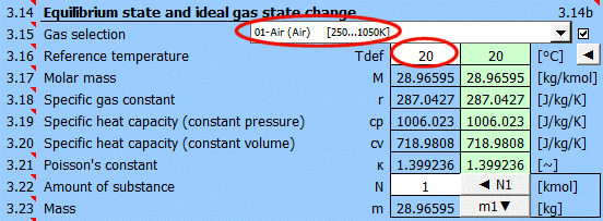
Enter properties for atmospheric pressure of 101kPa.

Enter the new pressure 20MPa = 20000kPa and press the button.

The result is the new mass of the cylinder's contents.

The mass will increase by 3.565 - 0.0182 = 3.5468kg.
Air is in a cylinder under a piston. 300kJ of heat is added to the cylinder. Determine the change in T and V, p1=p2.
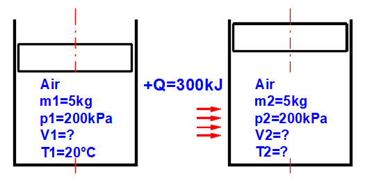
Select air as the working substance and set the temperature.

1. Enter values for m1, p1, T1.
2. Press the "◄" button to fill V1.
3. Use the "►►" button to copy the values to other points.
4. Gradually change temperature T2 until the Q value is 300kJ.
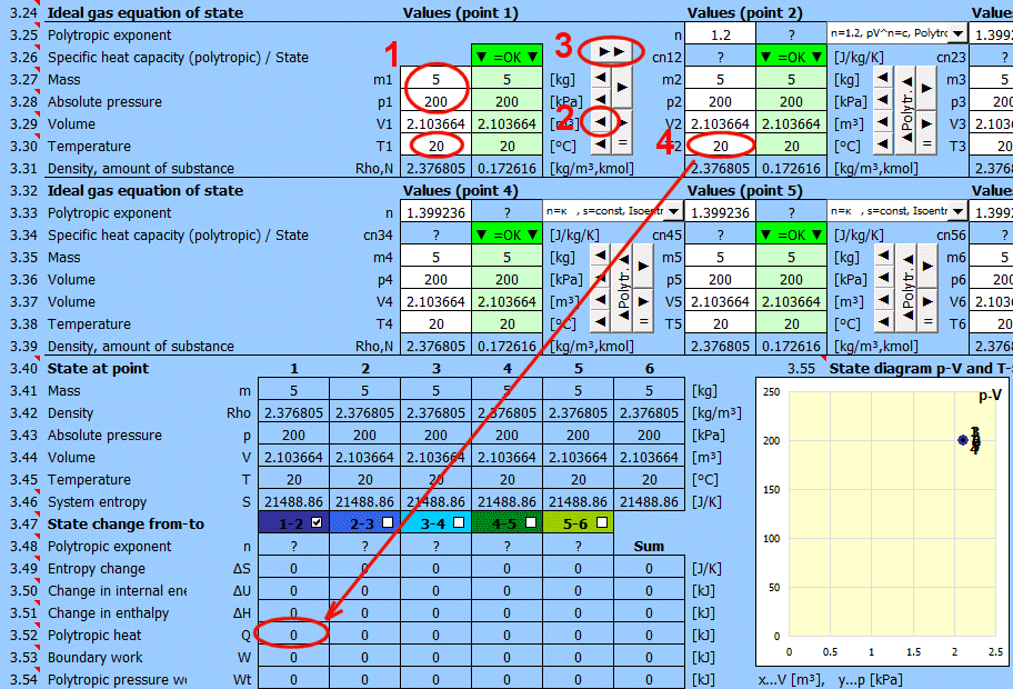
Press the "◄" button to fill V2.
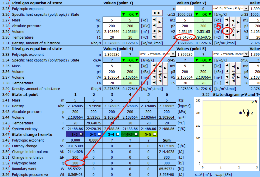
Two connected vessels contain air with different parameters. After opening the connecting valve, the gases will mix and then cool to a final temperature of 25C.
Determine the final pressure, temperature, energy change...
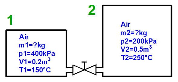
Select air as the working substance and estimate the temperature to be 100C.
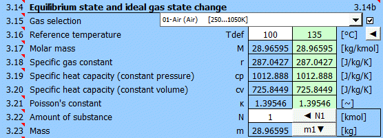
1. Set the parameters for vessel 1.
2. Fill in the corresponding gas mass m1.
3. Set the parameters for vessel 2.
4. Fill in the corresponding gas mass m2.
5. Press the button to calculate the parameters of the resulting mixture.
Point 3 shows the calculated gas parameters that will occur after mixing 1+2.
6. Transfer the resulting parameters to point 4.
7. Enter the final temperature of the entire system T4.
8. Fill in the corresponding gas pressure p4.
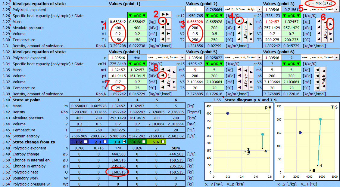
The change in energy (heat removed Q) is the change between 3-4. To cool the mixture (from point 3), 168kJ of heat must be removed.
During a polytropic process, all state variables (p, V, T) generally change. For a polytropic process in an ideal gas, the equation p * V^n = const applies.
For a reciprocating compressor: n = 1.2–1.3 (Process with partial heat
rejection, typical value for slow compressors with cooling).
Initial air parameters: m1 = ?, p1 = 150 kPa, V1 = 260 m^3, T1 = 27 °C.
It is compressed by a reciprocating compressor with a polytropic exponent n=1.2.
Final values: m2 = m1, p2 = ?, V2 = 80 m^3, T2 = ?
Select air as the working fluid and set the temperature.
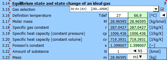
1. Set air parameters at initial point 1.
2. Fill in the corresponding gas mass m1 using the "◄" button.
3. Use the "►►" button to copy values to other points.
4. Fill in the final compressed volume V2.
5. Enter the desired polytropic exponent n=1.2.

6. Press the "Polytr." button.
This will calculate and fill in parameters p2 and T2 that satisfy the given
polytropic exponent n=1.2.
7. Results:
Final pressure p2 = 617 kPa
Final temperature T2 = 106.8 °C
Pressure work Wt = 62.2 MJ (17.27 kWh)
Heat rejected to surroundings Q = 25.8 MJ
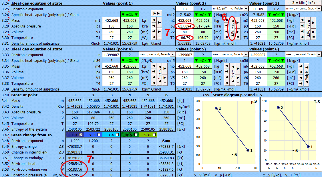
Calculation for a reciprocating compressor (1 liter displacement).
Working fluid: Air
Working volume: V1 = 0.001 m^3
Polytropic exponent: n=1.3 (Reciprocating compressor with partial heat
rejection, typical value for slow compressors with cooling).
Suction pressure: p1 = 100 kPa
Discharge pressure: p2 = 500 kPa
Suction air temperature: T1 = 25 °C
Clearance volume X: 5% => V3 = 0.00005 m^3 (Due to design constraints, complete
gas expulsion is not possible. Residual gas expands and reduces the volume of
intake gas).
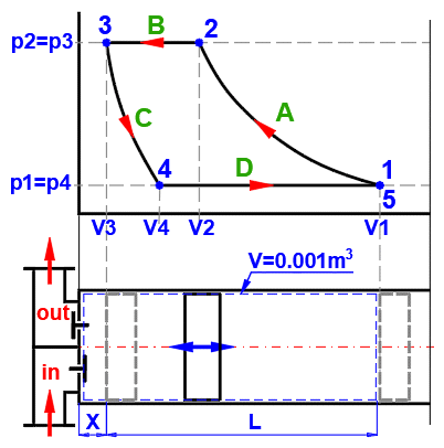
Select air as the working fluid and set the temperature.
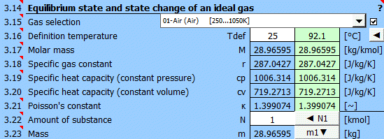
1. Set parameters at point 1 (p1 = 100 kPa, V1 = 0.001 m^3, T1 = 25 °C), fill in
m1 using the "◄" button.
2. Use the "►►" button to copy values to other points.
3. Enter discharge pressure p2 = 500 kPa and polytropic exponent n=1.3.
4. Press the "Polytr." button.
This will calculate and fill in parameters V2 and T2 that satisfy the given
polytropic exponent n=1.3.
5. Copy results to point 3 using the "►" button.
6. Enter final discharge volume V3 = 0.00005 m^3 and fill in m3 using the "◄"
button.
7. Copy results to point 4 using the "►" button.
8. Enter suction pressure p4 = 100 kPa and polytropic exponent n=1.3.
9. Press the "Polytr." button.
This will calculate and fill in parameters V4 and T4 that satisfy the given
polytropic exponent n=1.3.
The gas expands to state p4 = p1 (suction pressure).
10. Copy results to point 5 using the "►" button.
11. Enter final intake volume V5 = 0.001 m^3 and fill in m5 using the "◄"
button.
12. Enable display of the state in the p-V diagram. (Transition curves are shown
as straight lines).
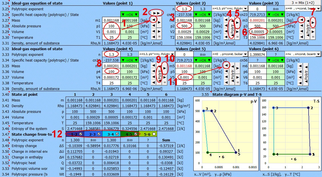
Water flows through a circular cross-section steel pipe with an
internal diameter of d=102 mm, wall thickness of 3 mm, and length L=200 m at a
temperature of T1 = 90 °C and velocity v1 = 0.1 m/s. The pipe is insulated with
20 mm thick mineral wool, an outer PVC layer 1 mm thick, and painted white. The
pipe is located outdoors and exposed to air flow at a temperature of T2 = 10 °C
with a velocity of v2 = 3 m/s. The pipeline is exposed to solar radiation with
an intensity of 1000 W/m^2.
Solve for the heat loss and the water temperature at the end of the pipe.
1. Enter temperatures T1 and T2.
2. Select wall type.
3. Define wall layers sequentially (dimensions and physical properties).
Materials can be selected from list [4.7] and added using the "Add" button.
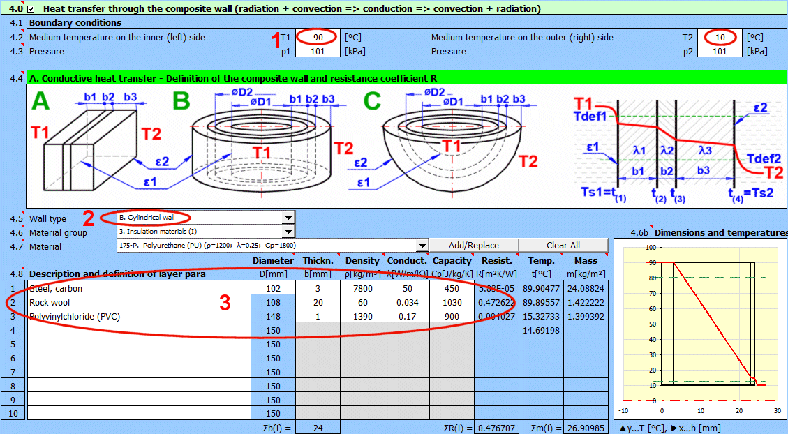

4. Select working medium 1 and 2.
5. Select flow type = shape of the wetted surface.
6. Enter flow velocity and dimensions.
7. Press the button for iterative result calculation.
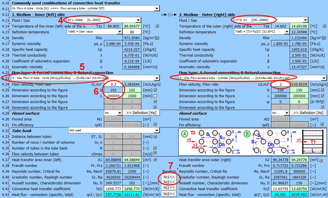
We are solving for a closed profile, so it is not necessary to deal with radiation on the inner side of the pipe (medium 1).
8. Select surface type, or directly enter emissivity ε2
at [4.45].
9. Select heat radiation to space.
10. Enter radiation intensity and select "*
ε" from the dropdown list - emissivity from [4.45] is
used.
11. Choose the size of the irradiated area Ai2 relative to area A2. (The sun
does not irradiate the entire pipe surface).
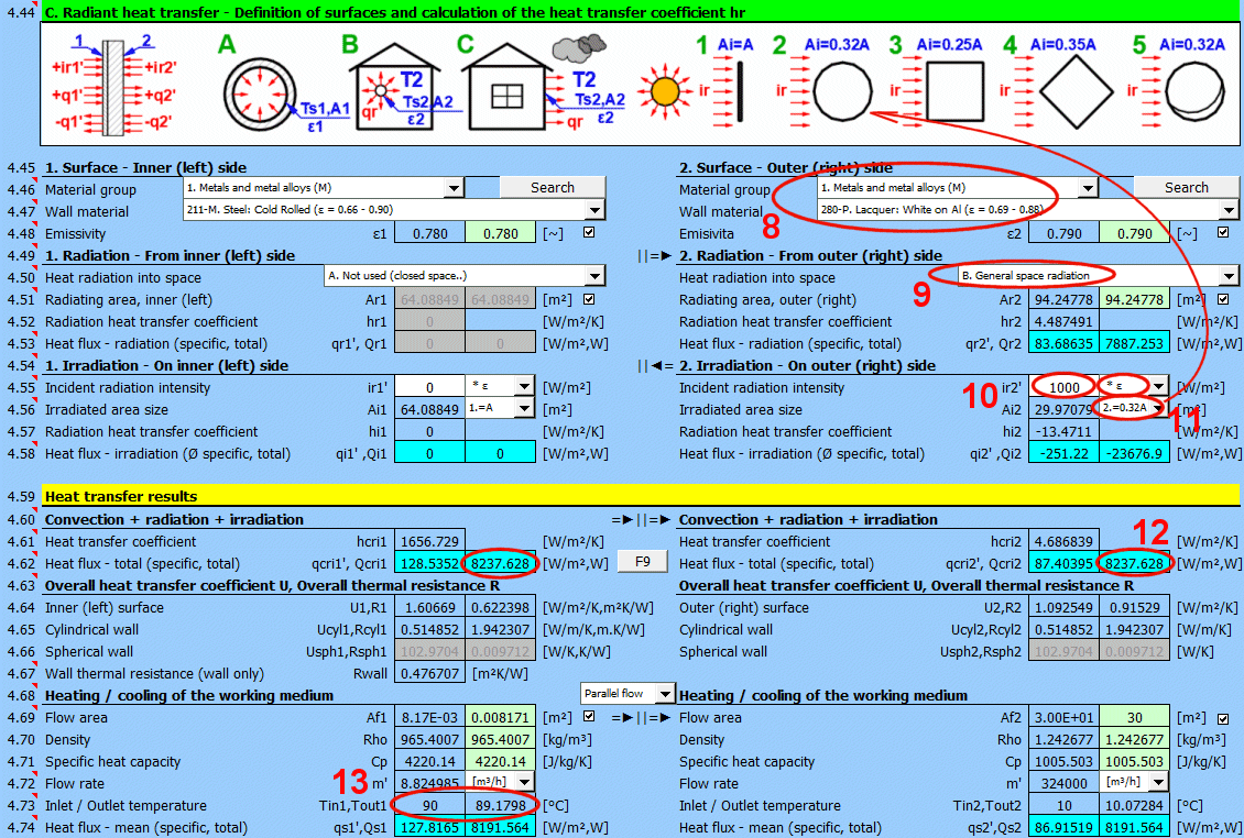
12. The resulting losses are 8237 W.
13. The temperature at the end of the pipeline is approximately 89.2 °C.
Try changing the top coat (emissivity ε2 [4.47, 4.48]) for both the sun-irradiated pipe and the non-irradiated pipe (ir2 = 0 W/m^2 [4.51]).
1. Name the current heat transfer solution.
2. Add a description of the solution.
3. Add the current solution to the list on the "Walls" sheet.
4. Select a solution from the list of saved solutions.
5. Load complete data. Current values will be overwritten with values from the
selected solution.

Solutions are saved to the "Walls" sheet. One row contains one saved
solution.
The "Walls" sheet is freely accessible and can be edited normally using Excel
tools (e.g., deleting unnecessary solutions - rows).
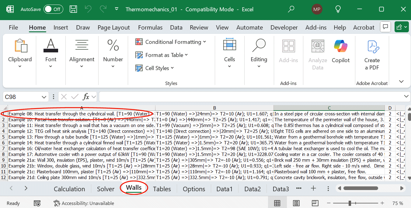
If you need to retrieve a specific value and use it in your own formula, the `GetWallProp` function is available.
Syntax:
GetWallProp(ID; value_name)
ID ... Row number on the "Walls" sheet containing the saved solution.
value_name ... ... Name of the value you want to retrieve.
Example:
=GetWallProp(1;"Date") ... Returns the date when the solution was added to the
list.
=GetWallProp(1;"T1") ... Returns the temperature of medium 1 - T1 in [°C].
=GetWallProp(1;"U1") ... Returns the overall heat transfer coefficient U1 in
[W/m²/K].
A common task may be to determine heat transfer parameters if you know some values (e.g., from measurements) and do not want to solve the complete heat transfer through the wall.
The temperature of a house perimeter wall 3.5 m high and 20 m long was measured with a thermal camera at Ts1 = 3 °C. The ambient air has a temperature of T1 = 0 °C and flows along the wall at a speed of 3 m/s.
Determine the overall heat transfer coefficient U and the total heat flux Q.
1. Enter the flowing air temperature T1 = 0 °C (Temperature T2 can be chosen
arbitrarily).
2. Select a planar wall.
3. Choose a wall material (its parameters do not matter).
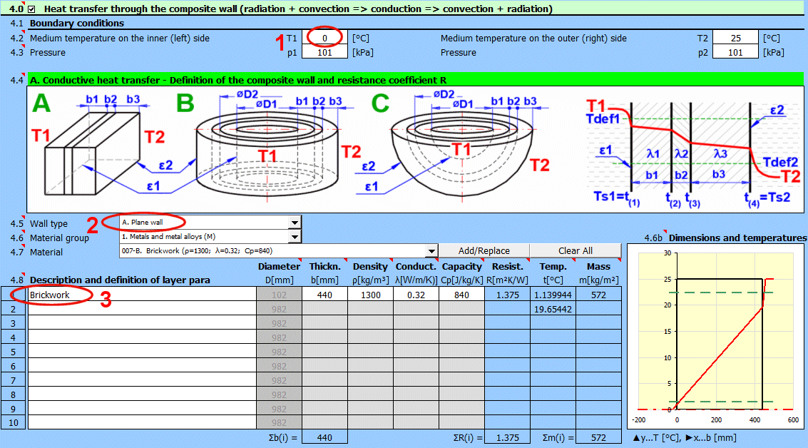
4. Select air as the working medium.
5. Uncheck the automatic filling of wall temperature Ts1. This will interrupt
the complex calculation, and only the left side of the wall is solved.
6. Enter the wall temperature Ts1 = 3 °C.
7. Select forced flow around a planar surface.
8. Enter flow velocity v1 = 3 m/s.
9. Enter surface dimensions.
10. Press the button to iterate hc1.
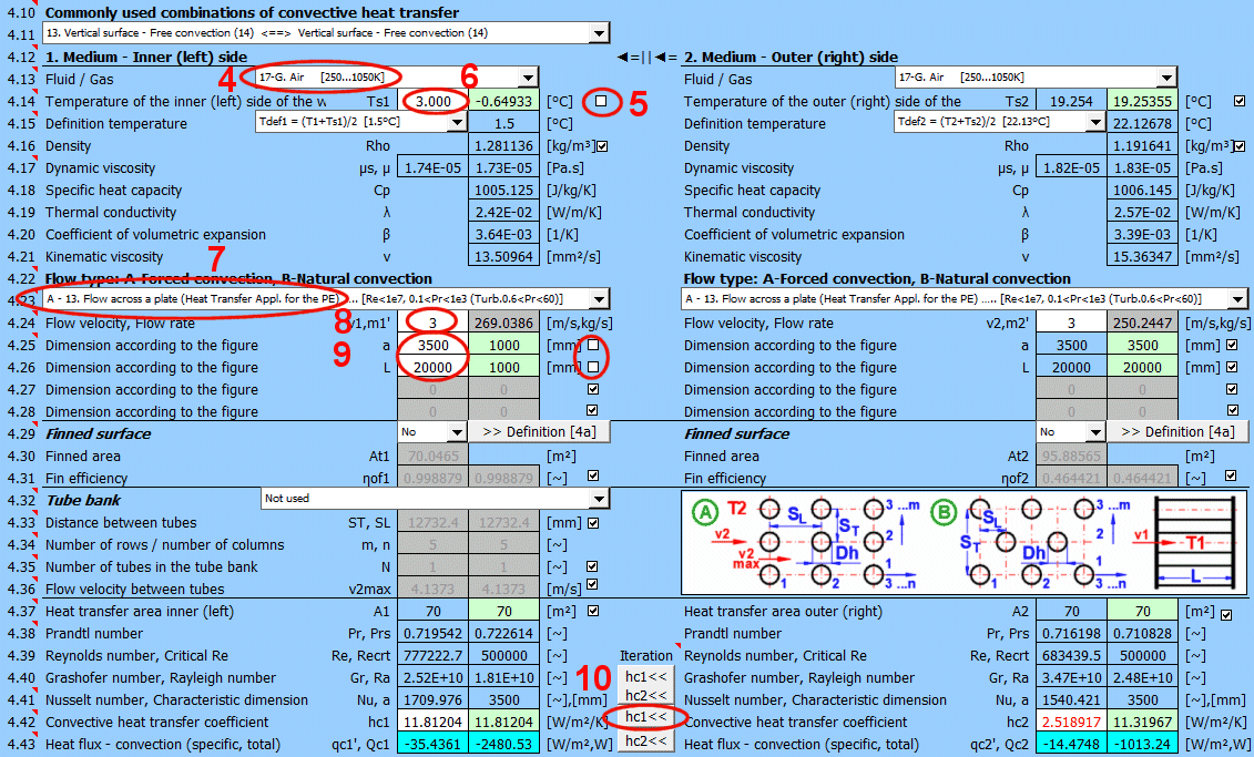
11. Choose the wall surface material.
12. Or directly enter the surface emissivity.
13. Select outdoor radiation.
14. You will get the total heat flux through the wall Q1 and the overall heat
transfer coefficient U1.
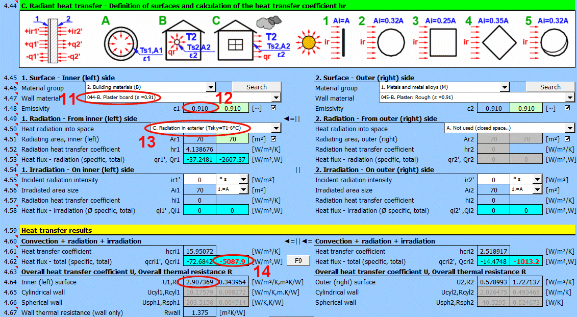
Try changing the top coat (emissivity ε2 [4.47, 4.48]).
For various cryogenic tanks, thermoses, etc., a wall with a vacuum on one side is often used.
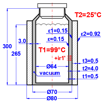
A thermos with a volume of 0.85 L has a cylindrical wall composed of t1 = 0.5 mm steel sheet, t2 = 4.0 mm insulation, and t3 = 0.5 mm PVC casing. There is a vacuum on the inner side of the wall. On the outer side is air at a temperature of 25 °C. The cylindrical wall has an inner diameter D = 70 mm and height L = 300 mm. Inside the thermos is a container with water at a temperature of 99 °C. The vacuum thickness is 3 mm. Radiation to the inner wall is 45 W/m^2 (from calculation in section [7.0]).
Determine the overall heat transfer coefficient U and the total heat flux Q.
Accepted simplification: Heat transfer through the side wall is solved; the effect of the bottom is compensated by using a height of 300 mm.
1. Enter temperatures T1 = 99 °C and T2 = 25 °C.
2. Select cylindrical wall.
3. Define the individual wall layers.
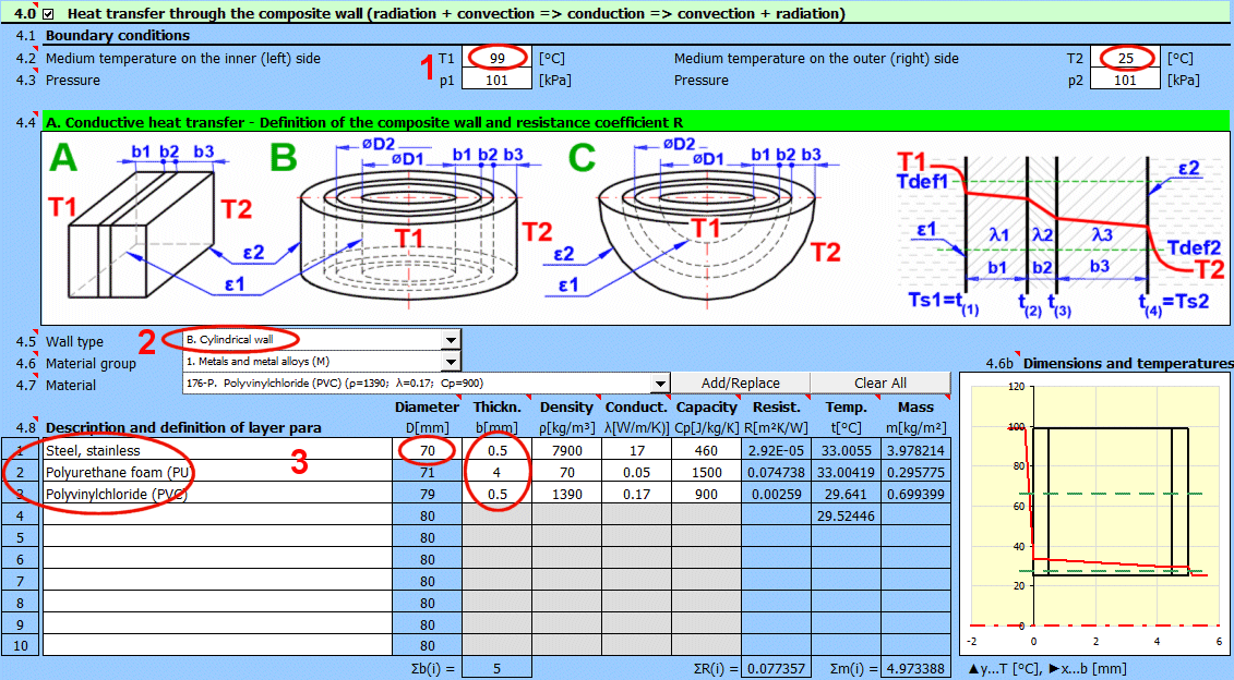

4. Select working medium 1 and 2.
5. Select flow type = shape of the wetted surface.
6. Enter the dimensions of the wetted container.
7. Press the button for iterative result calculation.
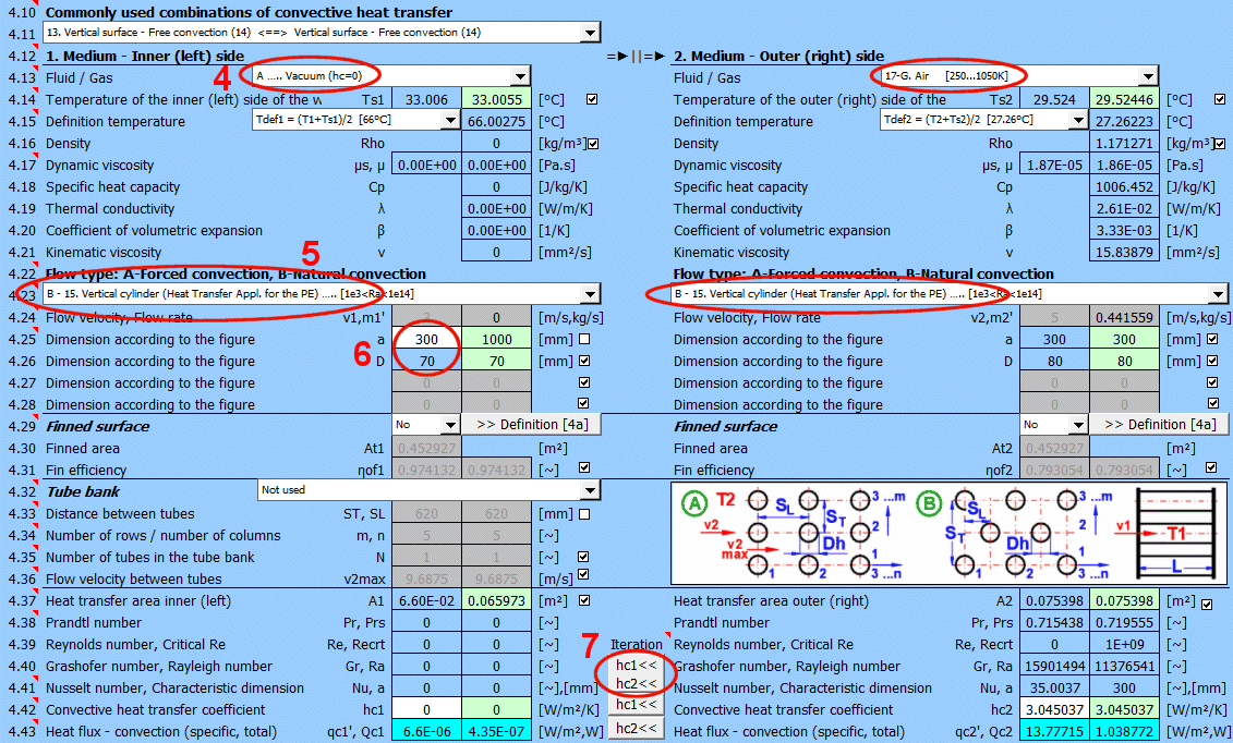
It is necessary to solve for radiation to space for the outer surface.
8. Select surface type, or directly enter emissivity ε2 = 0.92 at [4.45].
9. Select heat radiation indoors.
Irradiation of the inner wall surface.
10. Radiation to space is not solved - a closed space is being addressed.
11. In section [7.0], the radiation intensity ir1 = 45 W/m^2 is calculated
(Example 18 below) for wall emissivity ε1 = 0.15, so choose a multiplier of "*
1".
12. The entire inner surface is irradiated, select option "1.=A".
13. Values q, Q, and U can be used in further calculations (Example 15 below).
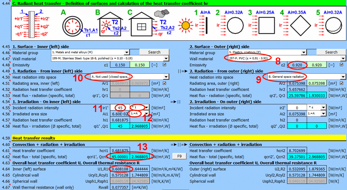
Analysis of an electric power generator with TEG modules and a heat sink cooled by air.
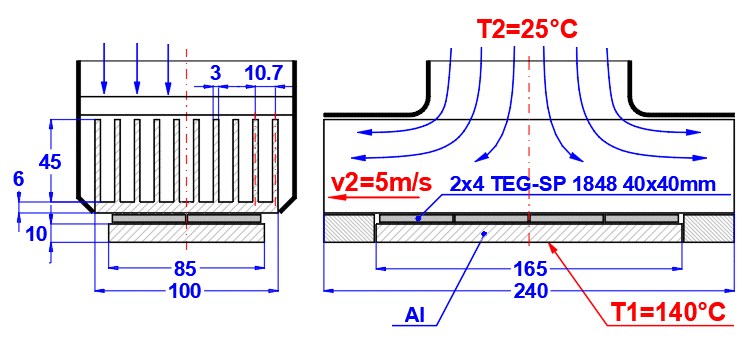
Eight TEG modules are attached on one side to an aluminum plate with dimensions 85 x 165 x 10 mm. On the other side, they are attached to an aluminum heat sink with dimensions 100 x 240 x 51 mm with ten fins and a base thickness of 6 mm. The aluminum plate is in contact with a heat source at a temperature of T1 = 140 °C. Air flows through the heat sink at a temperature of T2 = 25 °C with a velocity of 5 m/s. The thermal conductivity of a TEG module is 1.5 [W/m/K].
Determine the temperature of the TEG module on the hot and cold sides.
1. Enter temperatures T1 = 140 °C and T2 = 25 °C.
2. Select a planar wall.
3. Define the individual wall layers according to the figure.
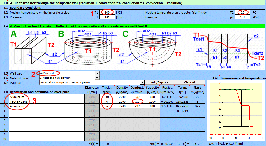

4. Select working medium 1 and 2 (Medium 1 - contact connection to the heat
source).
5. Enter the dimensions of the contact plate.
6. Select flow type (Forced flow around a plate = air flow in the heat sink).
7. Enter the dimensions of the heat sink footprint and air flow velocity.
8. Enable the use of a finned surface and define its dimensions in section
[4a.0].
9. After defining the fin dimensions, press the button for iterative result
calculation.
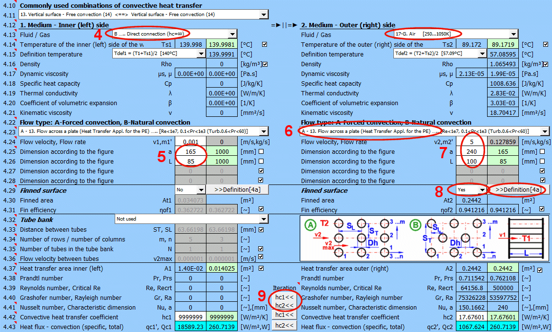
10. Select rectangular fin shape.
11. Enter dimensions and number of fins. The suggested number of fins is
calculated from the width of the finned area [4a.5] and the distance between
fins [4a.9].
12. Fin efficiency is calculated (used for calculating the heat transfer
coefficient [4.29, 4.39]).
13. The wetted area, which is increased by the fins, is calculated and used
instead of the original value [4.34].
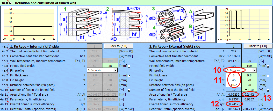
In this calculation, it is not necessary to consider radiation; parameters must be set accordingly.
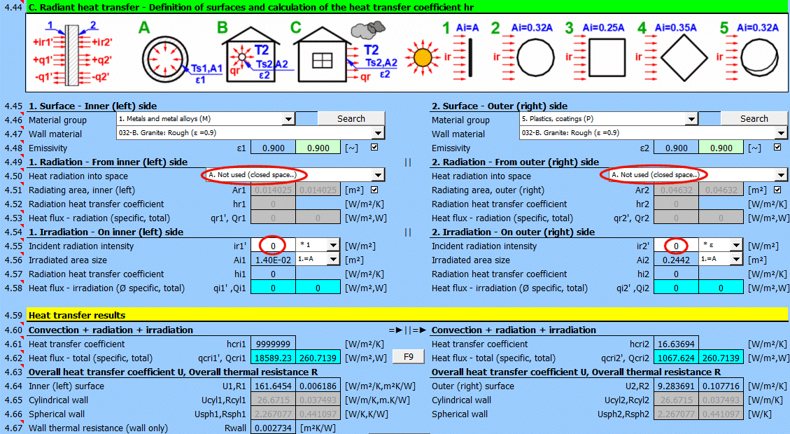
The required results (TEG module wall temperatures) can be found in table [4.8].

Conclusion: The temperature difference is 50 °C. Based on catalog data, for this temperature difference, the power of a single module is approximately 1 W, for 8 modules then 8 W. To increase the temperature difference, it would be necessary to significantly increase the heat sink area (more thin and tall fins) or use, for example, water cooling.
Heat transfer calculation in a tube bundle.
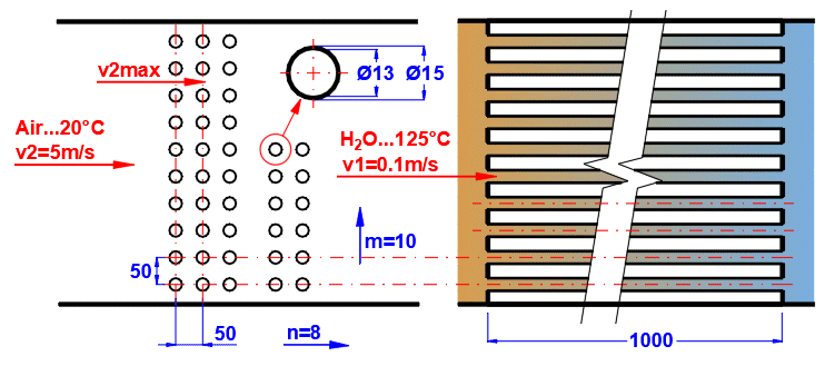
Water from a geothermal well at a temperature of T1 = 125 °C flows through the tubes at a velocity of 0.1 m/s. The steel tubes are in a bundle of 10 rows, 8 columns. The inner tube diameter is D1 = 13 mm, outer diameter D2 = 15 mm. Air enters the tube bundle at a temperature of T2 = 20 °C at a velocity of 5 m/s.
Determine the outlet air temperature and the heat exchanger power.
1. Enter temperatures T1 = 125 °C and T2 = 20 °C.
2. Select cylindrical wall.
3. Define tube dimensions and material.
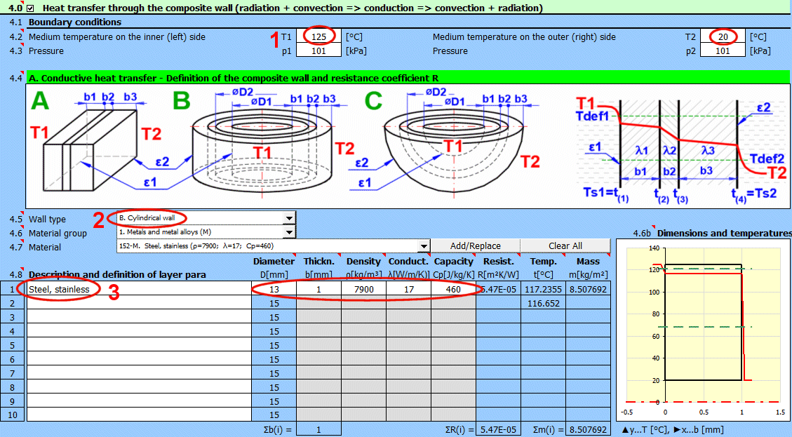

4. Select working medium 1 and 2.
5. Select flow type (Water flows through the tube, Air flows around the tube).
6. Enter flow velocities and inner and outer tube dimensions.
7. Enable and select tube arrangement in the bundle.
8. Enter distances between tubes and their number according to the figure.
9. After defining the dimensions, press the button for iterative result
calculation.
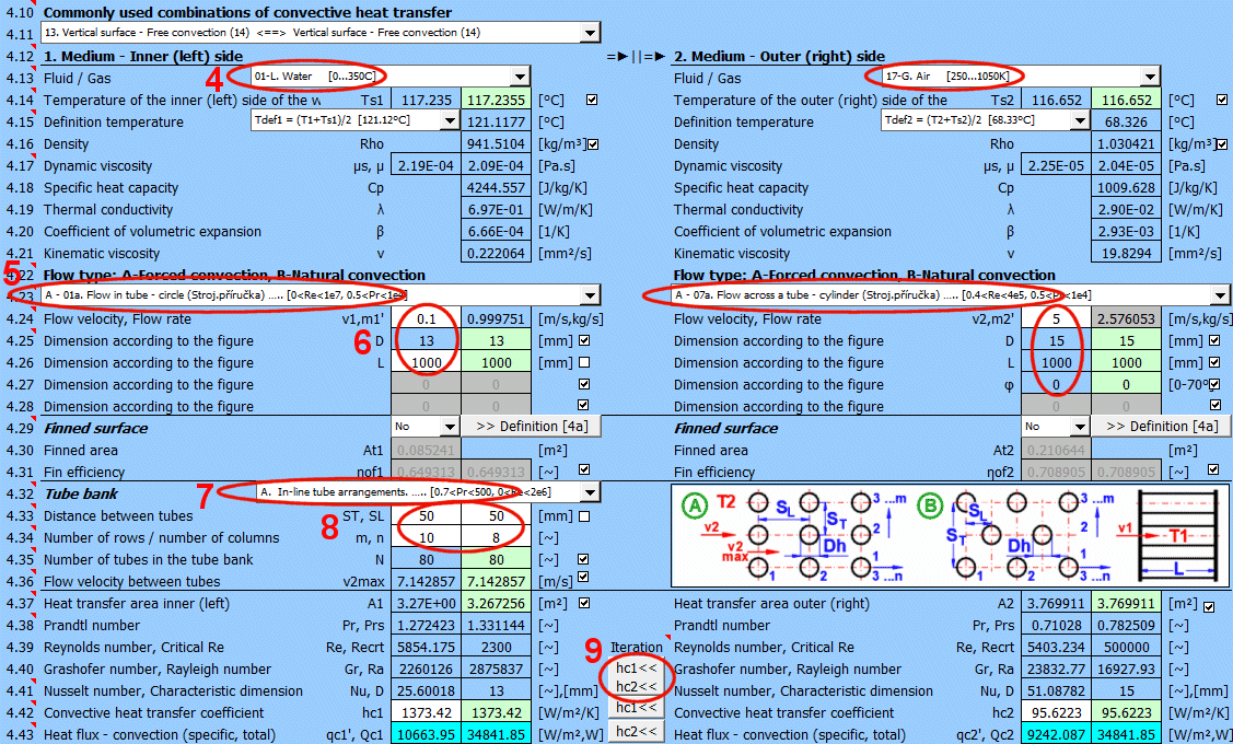
In this calculation, it is not necessary to consider radiation; parameters must be set accordingly.
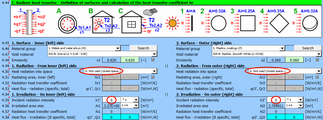
10. Select type of mutual flow - Counter-flow (More options are in the Heat
Exchangers chapter).
11. When the checkbox is selected, predefined values for Af, Rho, Cp are used.
The program attempts to suggest them based on the values entered above.
12. If the predefined values are not suitable, you can enter your own values
after unchecking the checkbox (11).
13. The outlet air temperature is 30.5 °C and the power is just under 32 kW.

Conclusion: The air temperature increase of 10 °C is relatively low. For a water-air heat exchanger, it would be unequivocally more advantageous to use finning.
In the previous example, unfinned tubes were used. In this example, we will use fewer tubes with larger dimensions and with finning.
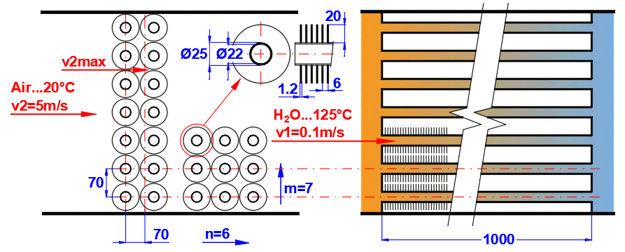
Water from a geothermal well at a temperature of T1 = 125 °C flows through the tubes at a velocity of 0.1 m/s. The steel tubes are in a bundle of 7 rows, 6 columns. The inner tube diameter is D1 = 22 mm, outer diameter D2 = 25 mm. Air enters the tube bundle at a temperature of T2 = 20 °C at a velocity of 5 m/s. The tubes are equipped with fins. Fin thickness t = 1.2 mm, fin height hf = 20 mm, and pitch s = 6 mm. The maximum number of fins n = 167 is used.
Determine the outlet air temperature and the heat exchanger power.
1. Enter temperatures T1 = 125 °C and T2 = 20 °C.
2. Select cylindrical wall.
3. Define tube dimensions and material.
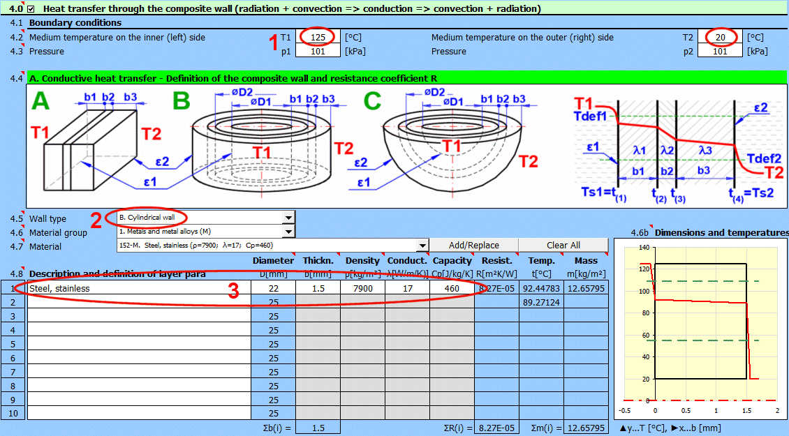

4. Select working medium 1 and 2.
5. Select flow type (Water flows through the tube, Air flows around the tube).
6. Enter flow velocities and inner and outer tube dimensions.
7. Enable the use of a finned surface and define its dimensions in section
[4a.0].
8. Enable and select tube arrangement in the bundle.
9. Enter distances between tubes and their number according to the figure.
10. After defining the dimensions, press the button for iterative result
calculation.
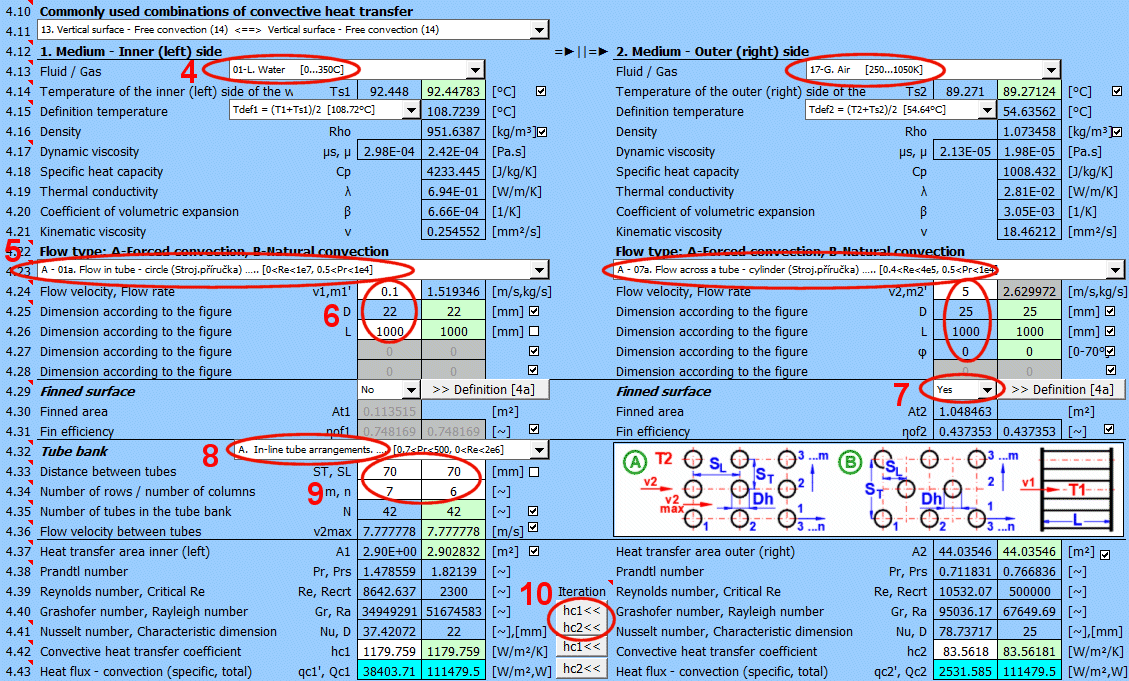
11. Select rectangular fin shape.
12. Enter dimensions and number of fins. The suggested number of fins is
calculated from the width of the finned area [4a.5] and the distance between
fins [4a.9].
13. Fin efficiency is calculated (used for calculating the heat transfer
coefficient [4.29, 4.39]).
14. The wetted area, which is increased by the fins, is calculated and used
instead of the original value [4.34].
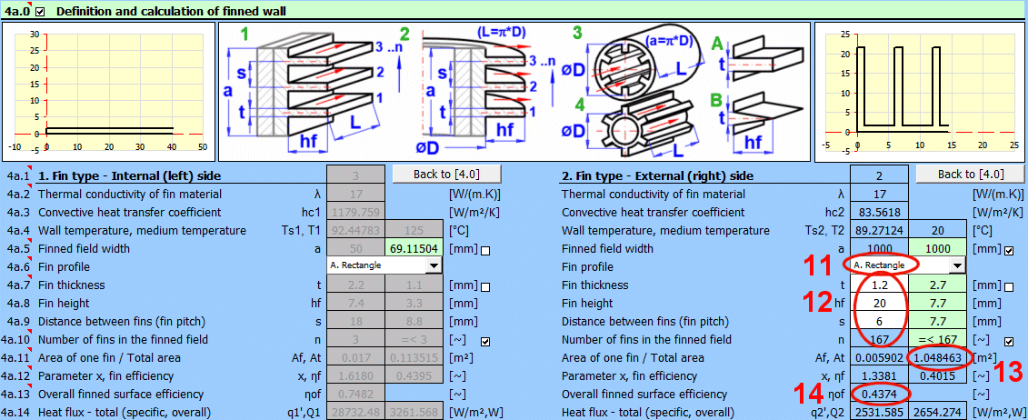
In this calculation, it is not necessary to consider radiation; parameters must be set accordingly.
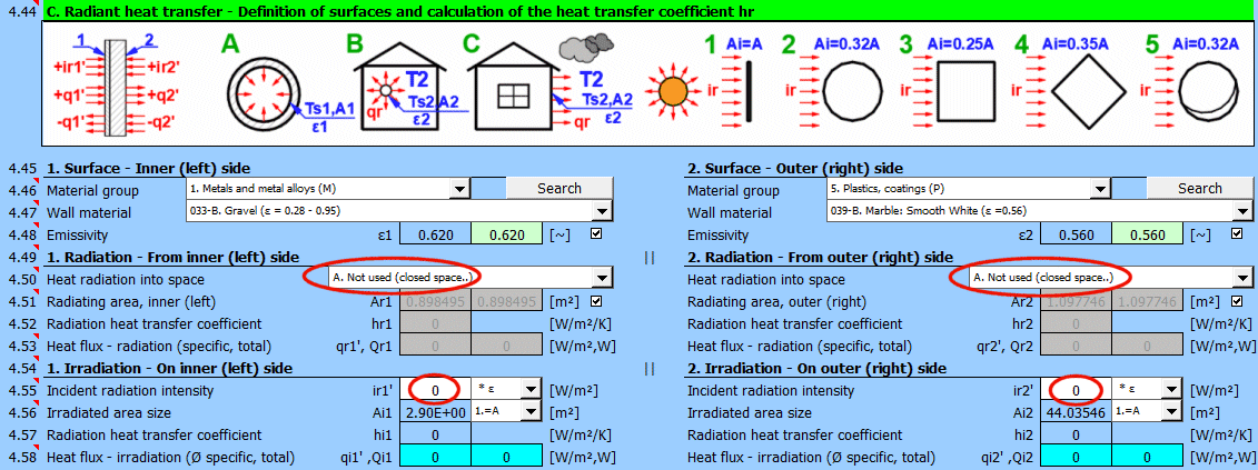
15. Select type of mutual flow - Counter-flow (More options are in the Heat
Exchangers chapter).
16. When the checkbox is selected, predefined values for Af, Rho, Cp are used.
The program attempts to suggest them based on the values entered above.
17. If the predefined values are not suitable, you can enter your own values
after unchecking the checkbox (16).
18. The outlet air temperature is 49.8 °C and the power is 88 kW.

Conclusion: The air temperature increase of 30 °C is three times that of the previous example, with half the number of tubes.
From Example 11, we know the overall heat transfer coefficient U = 0.6081 [W/m²/K] and the inner area A = 0.0659 [m²]. The initial liquid temperature (water) T1s = 99 °C. Ambient temperature T2 = 25 °C. Liquid mass is 0.85 kg.

Determine the cooling time of the liquid from temperature T1s = 99 °C to temperature T1e = 39 °C.
1. Select the liquid from the list. If the liquid is not in the list, uncheck
the checkbox and enter the Cp value.
2. Check / uncheck the checkbox. When checked, current values from section [4.0]
are used.
3. Fill in the required input values.
4. The cooling time to 39 °C is 41.5 hours. This corresponds to user tests of
mid-range thermoses.
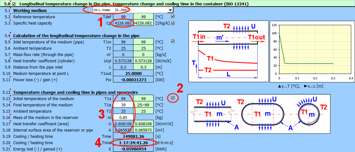
A tubular heat exchanger is used for oil cooling. The mass flow rate of cooling water in the inner tube is m1' = 0.25 kg/s, the mass flow rate of oil in the outer annular section is m2' = 0.15 kg/s. Water enters the heat exchanger at a temperature of T1in = 20 °C, oil at a temperature of T2in = 98 °C. The overall heat transfer coefficient for the cylindrical wall is 3.25 W/m/K.
A desired oil outlet temperature T2Out = 62 °C is required. Determine the water outlet temperature and the length of the heat exchanger for a counter-flow tubular heat exchanger.
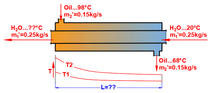

1. Select heat exchanger type.
2. If you decide to load data from the wall definition in section [4.0], select
the appropriate definition and load with the "Load" button.

3. Select working medium 1 and 2. If not in the list, enter Cp value directly
[6.7].
4. Enter parameters for medium 1.
5. Enter parameters for medium 2.
Values Q1 and Q2 [6.13] will most likely be different and highlighted in red. It
is necessary to solve the energy balance. The green fields show calculated
values which, when used, ensure that Q1 = -Q2.
6. Press the button to transfer the calculated value to T1Out. The water outlet
temperature T1Out = 31 °C.

After solving the energy balance, the pipe length (or area) can be determined.
7. Select calculation type B. In this case, you are solving for the heat
exchanger length and know Ucyl [W/m/K].
8. Enter the overall heat transfer coefficient for the tube Ucyl. If you loaded
values from the wall calculation (2), this value is in the green field.
9. The calculated length is L = 66 m.
10. If you know the tube diameter, you can convert the length to the heat
transfer area.
11. If you want to include fouling of the heat exchanger during operation in the
calculation, enter the fouling coefficient Rf and reduce the value of Ucyl
[6.21] by 4% [6.36].
12. Use the "▲U" button to set the corrected Ucyl value. The pipe length for the
heat exchanger including fouling is then L = 69 m.
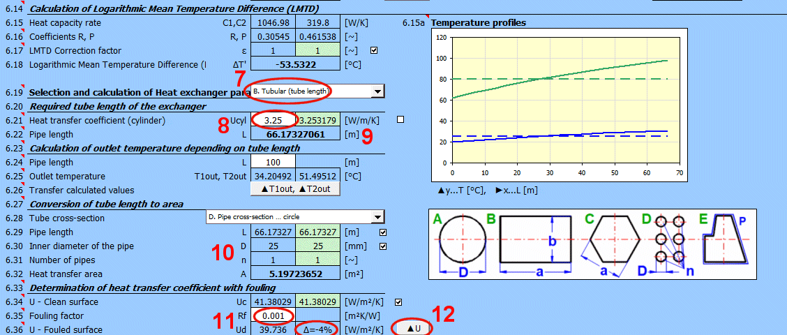
Cooling water in an automotive radiator. The radiator consists of 40 tubes
with an inner diameter of D1 = 5 mm and length L = 650 mm, which pass through
tightly arranged thin plates.
Water entering the heat exchanger has a temperature T1in = 90 °C and outlet
temperature T1Out = 65 °C. The water flow rate is m1' = 0.6 kg/s. Air enters the
heat exchanger at T2in = 20 °C and outlet temperature T2Out = 40 °C.
Solve for the air flow rate through the heat exchanger m2' = ??, Power Q = ??, and overall heat transfer coefficient U = ??, which must be achieved to meet the dimensional requirement of 40 tubes with a length of 650 mm.
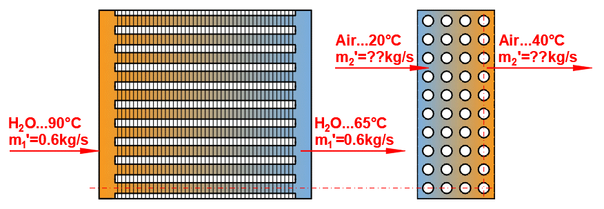

1. Select heat exchanger type.
2. If you decide to load data from the wall definition in section [4.0], select
the appropriate definition and load with the "Load" button.

3. Select working medium 1 and 2. If not in the list, enter Cp value directly
[6.7].
4. Enter parameters for medium 1.
5. Enter parameters for medium 2.
Values Q1 and Q2 [6.13] will most likely be different and highlighted in red. It
is necessary to solve the energy balance. The green fields show calculated
values which, when used, ensure that Q1 = -Q2.
6. Press the button to transfer the calculated value to m2'. The cooling air
flow rate m2' = 3.14 kg/s.
The cooling power of the radiator is 63 kW.

After solving the energy balance, the required overall heat transfer coefficient
can be determined. This can be either the area-based Upl [W/m²/K], relative to
the internal tube area, or the length-based coefficient Ucyl [W/m/K]. In this
case, we will choose the area-based solution (A).
Area Calculation. A = D1 * 3.14159 * L * n = 0.005 * 3.14159 * 0.65 * 40 =
0.4084 m^2.
7. For C-H type heat exchangers, a correction factor ε must be used. The
coefficient is automatically suggested from the inlet and outlet temperatures.
8. Select calculation type A. In this case, it is necessary to determine Upl
[W/m²/K] to achieve the defined area A.
9. Gradually change the value of Upl until the corresponding area A = 0.4084 m^2
is achieved.
10. You can verify the correct size by converting area A to tube length.
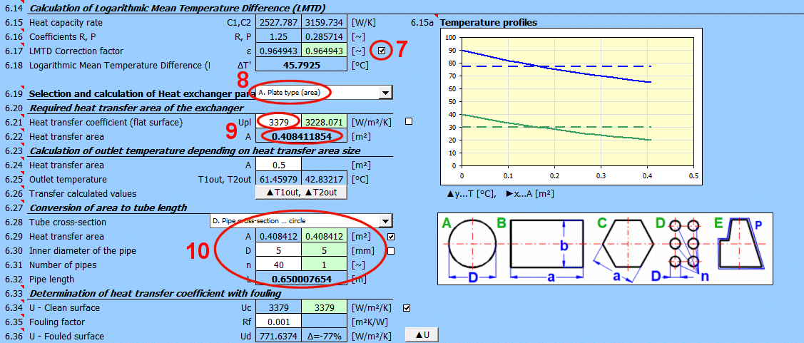
In Example 11, we need to determine the mutual heat flux between two concentric cylinders with a vacuum between them. The inner cylinder wall temperature is T1 = 99 °C, and the outer cylinder wall temperature is estimated to be T2 = 30 °C.

Determine the specific heat flux q21, which is necessary for solving Example 11.
1. Select two parallel surfaces.
2. Select surface type, or directly enter emissivity ε1 = ε2 = 0.15 at [7.5].
3. Enter temperature T1 = 99 °C.
4. Enter temperature T2 = 30 °C (initial estimate).
5. Enter dimensions of cylindrical surfaces.
6. The resulting specific heat flux q21 = 47 [W/m²].
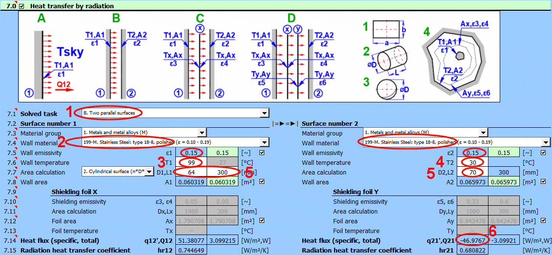
After substituting the value q21 = 47 [W/m²] into the wall heat transfer
calculation in section [4.0], we determine the exact wall temperature T2 = 33
°C.
After re-substituting T2 = 33 °C into this calculation, we obtain a more
accurate value q21 = 45 [W/m²].
A pipe with a diameter D1 = 200 mm, surface temperature T1 = 200 °C, and
emissivity ε1 = 0.93 is placed concentrically in a circular tunnel with a
diameter D2 = 2000 mm, surface temperature T2 = 20 °C, and emissivity ε2 =
0.736. Shielding between the surfaces is provided by a thin aluminum foil placed
concentrically with an emissivity ε3 = ε4 = 0.05. Determine the heat flux
between the pipe and the tunnel per 1 m of its length.
A) Without shielding.
B) Shielding foil has a diameter Dx = 300 mm.
C) Shielding foil has a diameter Dx = 1900 mm.

1. Select the type of problem to solve.
2. Enter the emissivity of surface 1 and 2.
3. Select the type of surface being solved.
4. Enter temperature and dimensions of surface 1 (pipe). Enter length 1 m.
5. Enter temperature and diameter of the circular tunnel (length is the same).
6. Heat flux per 1 m of pipe Q = 1370 W.

Values for wall 1 and 2 remain the same.
1. Change the type of problem to C.
2. Enter the emissivity of the foil ε3, ε4.
3. Enter the diameter of the shielding foil Dx = 300 mm.
6. Heat flux per 1 m of pipe Q = 56 W.

Values for wall 1 and 2 remain the same; only diameter Dx changes.
1. Enter the diameter of the shielding foil Dx = 1900 mm.
6. Heat flux per 1 m of pipe Q = 292 W.

Conclusion: The use of shielding foil can be an effective means of reducing heat transfer.
You are designing a pipeline through which a cooling liquid will flow. Your location is near Paris in an industrial area. You need to determine the maximum solar heat radiation and the total daily energy input.
1. Maximum solar radiation intensity is on June 21st at 12:00 PM.
2. The geographic latitude of Paris is \zeta = 48.9 °.
3. Set the surface tilt perpendicular to the sun \beta = 30 °.
4. Set the surface orientation to south \gamma = 0 °.
5. The altitude of Paris is Alt = 35 m.
6. Air pollution coefficient in the industrial area Z = 5.
7. Maximum solar radiation level for a clear sky under the selected conditions.
8. Total daily energy input on a defined planar surface (at points 3 and 4). The
input on a cylindrical surface will be slightly higher.
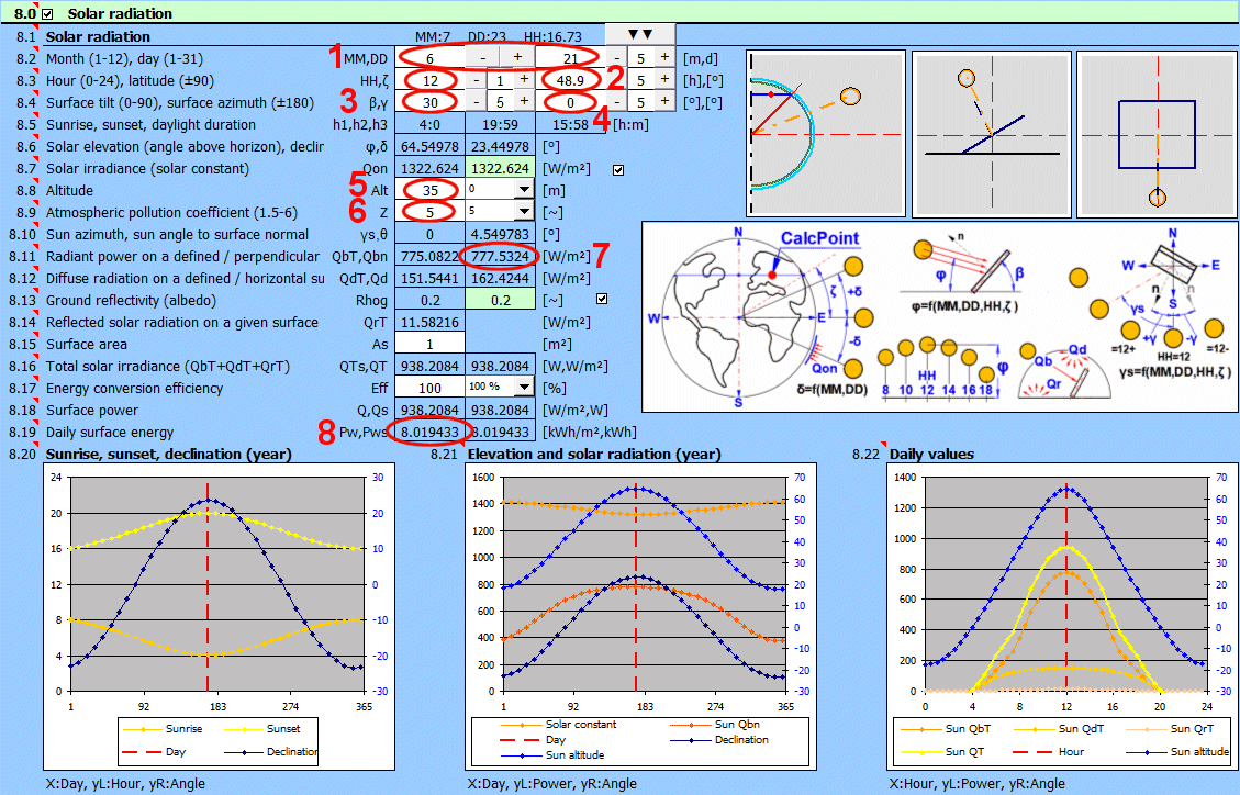
In a service building with a flat roof (floor plan 5 x 14 m).
Wall areas: Defined in the figure.
Overall heat transfer coefficients: Defined in the table.
External conditions: T4 = -10 °C, wind 10 m/s.
Required temperatures and conditions: T1 = 12 °C, T2 = 22 °C, T3 = 15 °C.
Input conditions: heat sources QH1 = 1000 W, QH2 = 2000 W, QH3 = 1500 W.
Both problems can be solved with the same mathematical model.
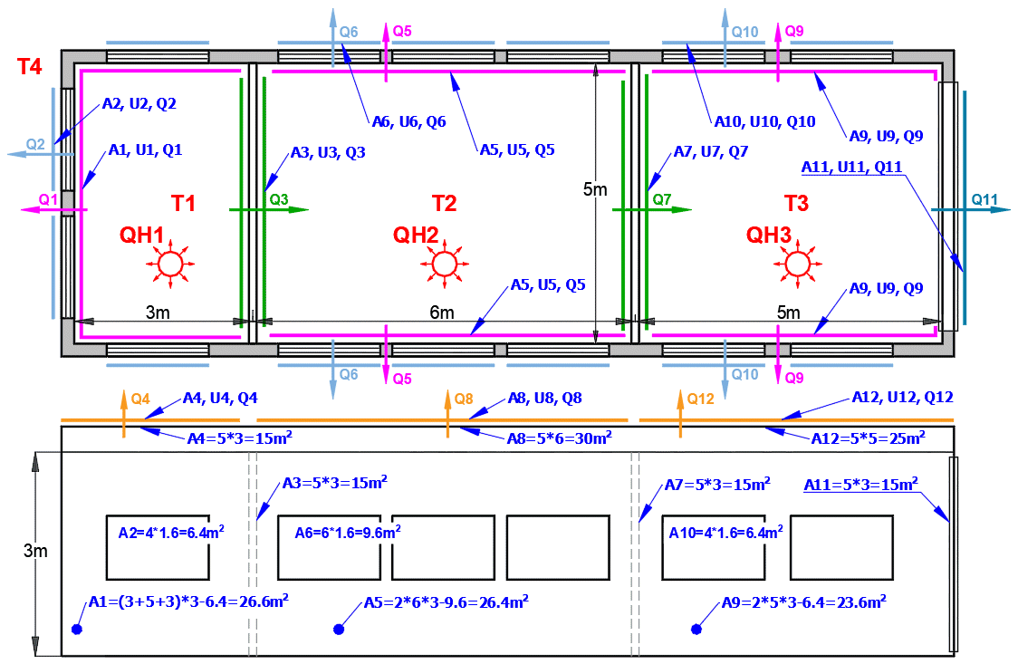
In section [4.0], the overall heat transfer coefficients U for individual walls
are calculated and saved in the list of solved walls.
1. Set which values from the solved walls will be transferred to the table.
2. Load wall information for individual rooms sequentially.
Of course, it is possible to enter U values directly, for example, from a
supplier's catalog.
3. Set the actual area for each wall according to the figure (A1 = 26.6, A2 =
6.4,.........).
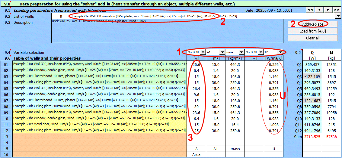
4. Define the heat flux Q for each wall in column Q according to the formula Q =
dT * A * U (dT ... temperature difference, A ... wall area, U ... overall heat
transfer coefficient).
Q1 = (T1 - T4) * A1 * U1
Q2 = (T1 - T4) * A2 * U2
Q3 = (T1 - T2) * A3 * U3
Q4 = (T1 - T4) * A4 * U4
............
5. Define conditions stating that the heat flux from each room must equal the
heat source power.
Q1 + Q2 + Q3 + Q4 - QH1 = 0
Q5 + Q6 + Q7 + Q8 - Q3 - QH2 = 0
Q9 + Q10 + Q11 + Q12 - Q7 - QH3 = 0
6. Set appropriate initial values for heat sources (e.g., QH1 = 500, QH2 = 1500,
QH3 = 1500).
7. Set desired temperatures according to the assignment.
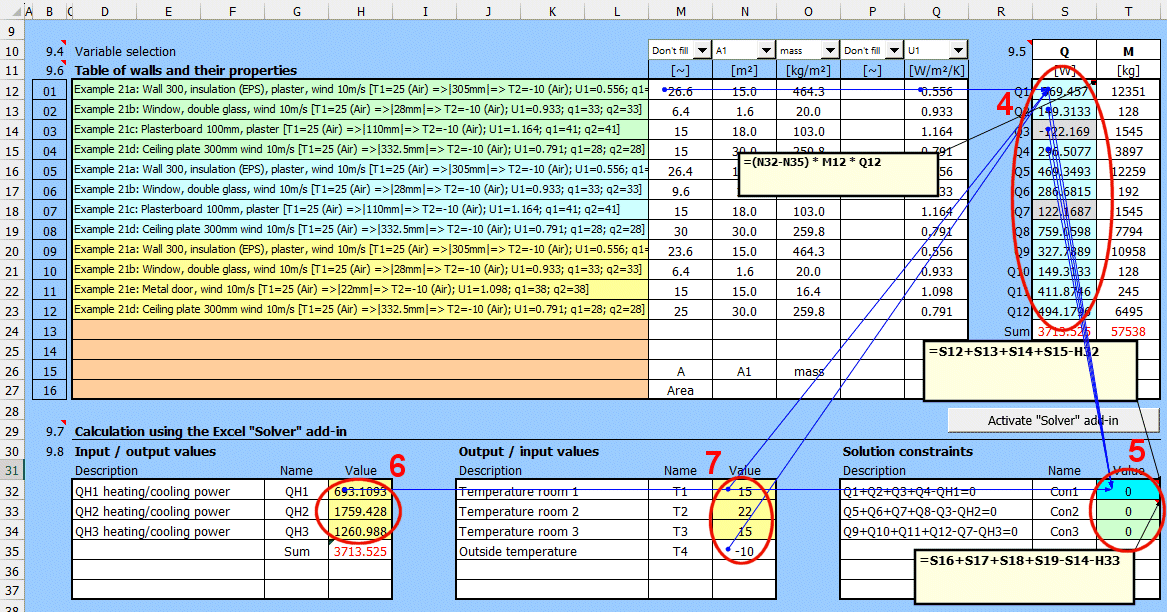
1. Launch the "Solver" add-in (Excel menu "Data").
2. Enter the cell and value to be achieved: "Set objective:".
3. Enter the cells to be changed: "By Changing Variable Cells:".
4. Add additional conditions to be met: "Subject to the Constraints:".
5. Start solving the problem: "Solve".
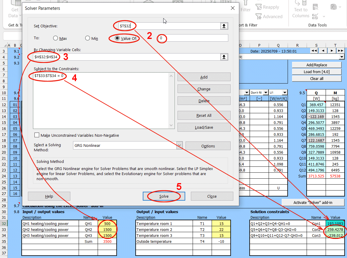
Upon completion of the solution, the desired values (3) and (4) should change,
and a dialog will appear.
1. Choose to keep the solution.
2. Confirm: "OK".
3,4. Solution results.
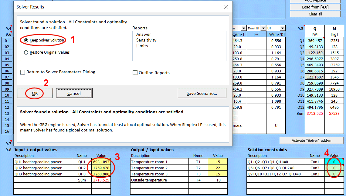
Task B is solved in the same way, where for the given heating powers (3), the room temperatures T1, T2, T3 are changed.
Information on setting of calculation parameters and setting of the language can be found in the document "Setting calculations, change the language".
General information on how to modify and extend calculation workbooks is mentioned in the document "Workbook (calculation) modifications".
Literature:
EN
[01] YUNUS A. ÇENGEL, AFSHIN J. GHAJAR: Heat and Mass Transfer: Fundamentals
& Applications, 5th Edition, McGraw-Hill Education.
[02] YUNUS A. ÇENGEL: Heat Transfer a Practical Approach, Second Edition.
[03] MORAN, M.J., SHAPIO, H.N.: Fundamentals of engineering thermodynamics. 8th
Edition New York: John Wiley a sons, 1990.
[04] DEWITT, BERGMAN, LAVINE: Fundamentals of Heat and Mass Transfer 6th Edition
[05] WARREN M.ROHSENOW, JAMES R.HARTNETT, YOUNG I.CHO: Handbook of Heat
Transfer, 3th Edition, McGraw-Hill
[06] SCHLUNDER, BELL, HEWITT, SPALDING: Heat Exchanger
Design Handbook, VDI-Verlag GmbH, 1983.
[07] LOIS THEODORE: Heat Transfer Applications for the
Practicing Engineer, John Wiley & Sons, Inc., 2011.
[08] MYER KUTZ: Heat-Transfer Calculations,
McGraw-Hill
[09] HOLMAN, J.P.: Heat Transfer, 10th. Edition, New
York: McGraw-Hill
[10] HOLMAN, J.P. Thermodynamics. 4th. New York:
McGraw-Hill Book Company, 1988. 780 s. ISBN 0-07-029633-2.
[11] MOHAMED M. EL-AWAD: Optimisation Analyses of
Fluid- Thermal Systems Using Excel,
[12] FRANK KREITH, RAJ MANGLIK, MARK BOHN: Principles
of Heat Transfer, Cengage Learning, Inc., 2011
CZ
[13] HORÁK VLADIMÍR, STŘEDA IVO: Mechanika tekutin
- Termomechanika, Strojírenská příručka, Scientia sro.
[14] RANEVI,K. Termodynamické tabulky. 1.vyd.
Bratislava: ALFA 1984. 313s. [L5] HAEK, P. Tabulky pro tepelnou techniku. 1 .vyd.
VB Ostrava, 1980, 247 s.
[15] SAZIMA,M., KMON1OEK,V., SCHNELER,J. Teplo. 1.vyd.
Praha: SNTL, 1989. 588 s. Technický průvodce. ISBN 80-03-00043-2.
[16] M.A.MICHEJEV: Základy sdílení tepla, Průmyslové
vydavatelství, 1952
[17] PETRAK,J., DVOAK, Z., KLAZAR, L., SYNEK, V.
Chiadivo R134a, (1.vyd.) VUT, 1993. 72s.
[18] MIROSLAV JÍLEK, ZDENĚK RANDA: Termomechanika -
sbírka příkladů, ČVUT, 2004
Standards:
ASTM C1340-2015 ... Estimation of Heat Gain or Loss Through Ceilings Under
Attics Containing Radiant Barriers...
ISO 12241:2022
Tepelněizolační výrobky pro zařízení budov a průmyslové instalace - Pravidla
výpočtu
Thermal insulation for building equipment and industrial installations —
Calculation rules
Isolation thermique des équipements de bátiments et desinstallations
industrielles — Méthodes de calcul
Wärmedammung an haus- und betriebstechnischen Anlagen — Berechnungsregeln
^